LiberIT Blog
Here are our latest updates:
-
Electronics
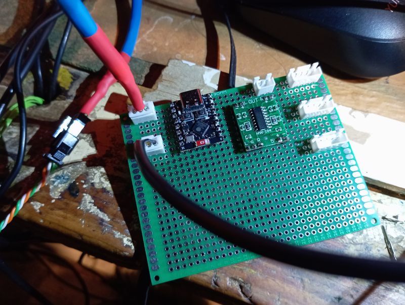
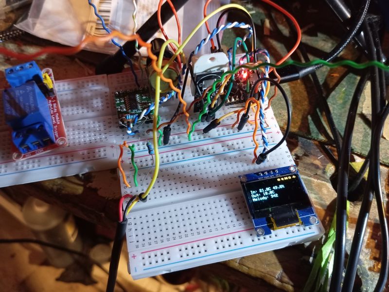
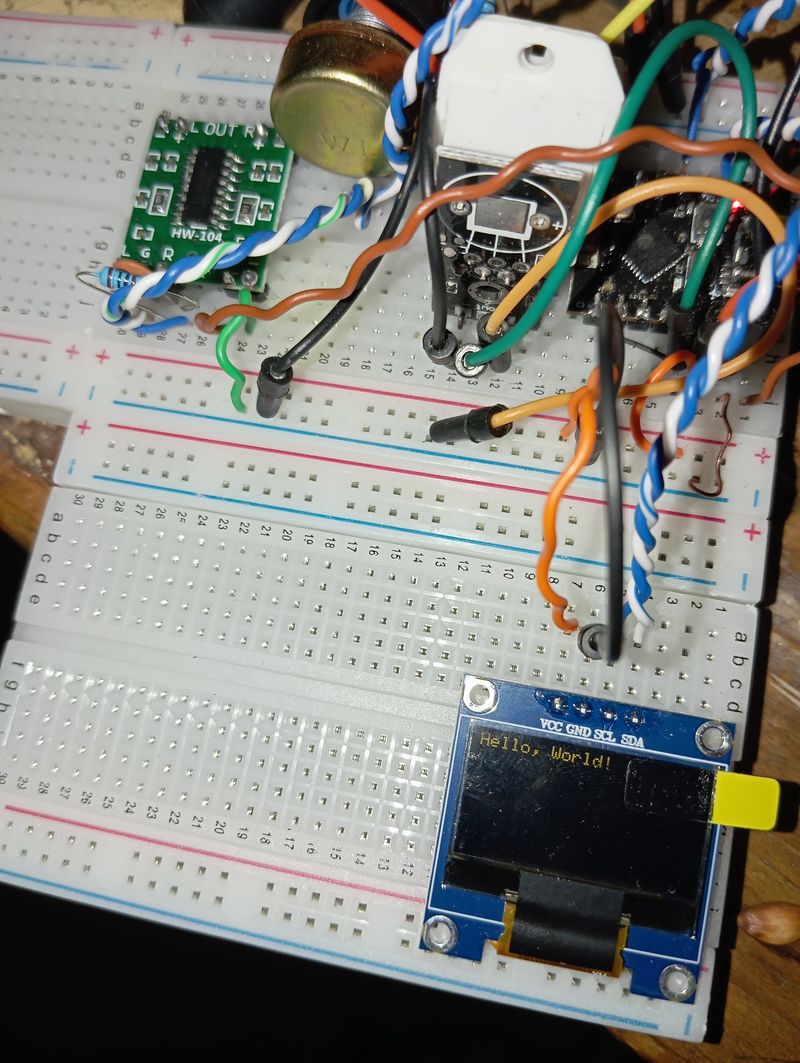
Submitted on: 1/19/2025, 9:03:05 AMAsk to BuyGot my w5500 ethernet module working in conjunction with other sensors and displays. Will be good to have hardline to the greenhouse that doesn't have good WiFi.
-
Electronics
Submitted on: 1/12/2025, 9:56:56 PMAsk to BuyThe Tale of King Amplifier and the River of Power
Once upon a time, in the prosperous kingdom of Amplifica, there stood the mighty Castle LM358, home to the wise and powerful King Amplifier. His job was simple but vital: take a small river flowing into the castle and amplify it into a roaring river that irrigated the vast fields of the kingdom. But King Amplifier didn’t work alone—he relied on clever engineering and careful design to keep everything in balance.
Let me tell you how the King, with the help of his Control Reservoir, the Feedback Aqueduct, and the Ground Ditch, decided whether to add more or less water to the mighty Output River.
The Layout of the Castle
The castle was an engineering marvel, with important gates and structures that kept the water flowing smoothly:
- Gate 3 (Input Gate): The Input River flowed into this gate, carrying a small but steady stream of water (the input voltage, (V_{\text{in}})).
- Gate 2 (Control Gate): Behind this gate lay the Control Reservoir, where the King monitored the water level. This reservoir was key to his decisions about how much water to release into the Output River.
- Gate 1 (Output Gate): The Output River gushed from this gate, amplified by the King’s work. The flow here (output voltage) powered the fields of Amplifica.
- The Sky Well (VCC): A magical source of energy that set the upper limit for the Output River. No matter what, the river could never rise higher than the level of the Sky Well.
- The Ground (Pin 4): The solid earth beneath the castle allowed water to safely drain away when needed, preventing overflow.
The King’s Feedback System
King Amplifier didn’t make decisions blindly. He relied on an ingenious system to control the flow:
- The Feedback Aqueduct (Resistor (R_f)): This aqueduct carried water from the Output River back to the Control Reservoir, allowing the King to monitor how much water he had already released.
- The Ground Ditch (Resistor (R_g)): This ditch let some water from the Control Reservoir drain to the ground, keeping the reservoir from overflowing and maintaining balance.
Together, the aqueduct and ditch created a loop of information, constantly telling the King whether to add more or less water to the Output River.
How the King Decided
The King always checked the water level in the Control Reservoir to make his decisions. Here’s how it worked:
-
If the reservoir was low:
- A low water level meant that the Output River wasn’t strong enough to bring back much feedback through the aqueduct.
- The King saw this as a signal to open the gates wider and send more water into the Output River.
-
If the reservoir was high:
- A high water level meant that the Output River was already strong, and plenty of water was flowing back through the aqueduct.
- The King saw this as a signal to reduce the flow and send less water into the Output River.
The balance of water flowing through the aqueduct and the ditch determined the reservoir level. The engineers knew this balance was critical, so they carefully sized both paths.
How the Aqueduct and Ditch Worked Together
The engineers designed the aqueduct and ditch to set the gain—the factor by which the Input River was amplified into the Output River. Here’s how they worked:
-
The Feedback Aqueduct (Resistor (R_f)):
- If the aqueduct was wide (low resistance), a lot of water flowed back from the Output River into the reservoir. This quickly filled the reservoir, signaling the King to reduce the flow into the Output River, which reduced the amplification.
- If the aqueduct was narrow (high resistance), less water flowed back, leaving the reservoir low. This signaled the King to release more water, increasing the amplification.
-
The Ground Ditch (Resistor (R_g)):
- If the ditch was wide (low resistance), a lot of water drained from the reservoir to the ground, lowering the reservoir level. This signaled the King to release more water, increasing the amplification.
- If the ditch was narrow (high resistance), less water drained, keeping the reservoir full. This signaled the King to release less water, reducing the amplification.
The engineers used a simple formula to design the aqueduct and ditch: [ G = 1 + \frac{\text{Size of Aqueduct}}{\text{Size of Ground Ditch}} ] This formula told the King how much to amplify the Input River.
An Example in Amplifica
One day, the Input River brought 1 liter per second (1 V) to the castle. The engineers set up the aqueduct and ditch with these sizes:
- Aqueduct (Feedback Resistor (R_f)): 10 liters per second
- Ground Ditch (Resistor (R_g)): 5 liters per second
Using the formula, the gain was: [ G = 1 + \frac{R_f}{R_g} = 1 + \frac{10}{5} = 3 ] The King amplified the Input River, sending an Output River of 3 liters per second (3 V) to the fields.
But if the engineers adjusted the aqueduct to 5 liters per second and the ditch to 10 liters per second, the gain would drop: [ G = 1 + \frac{5}{10} = 1.5 ] Now the Output River flowed at only 1.5 liters per second.
The Role of the Sky Well
The Sky Well (VCC) always reminded the King of his limits. No matter how strong the Input River was or how wide the aqueduct and ditch were, the Output River could never rise higher than the Sky Well’s level.
For example:
- If the Sky Well was set at 10 liters per second (10 V), and the system tried to create an Output River of 12 liters per second, the Sky Well would cap it at 10 liters, keeping the kingdom safe from flooding.
Why the Reservoir Level Was Key
The King didn’t directly measure the Input River. Instead, he relied on the Control Reservoir to tell him what to do:
- The reservoir level reflected the combined effect of the Input River, the aqueduct, and the ditch.
- If the reservoir was low, it meant the system needed more flow, and the King released more water into the Output River.
- If the reservoir was high, it meant the system had enough feedback, and the King held back, reducing the Output River.
The Kingdom Thrives
Through careful teamwork between the Input River, the aqueduct, and the ditch, King Amplifier managed the flow of water with precision. He amplified the Input River to power the fields, while the Sky Well kept the system safe. By watching the Control Reservoir, the King always knew when to add more water or hold back, keeping Amplifica prosperous and balanced.
And so, the kingdom of Amplifica flourished, thanks to the wisdom of King Amplifier and his engineers. 🌊👑
The end.
-
Electronics
Submitted on: 1/12/2025, 9:56:32 PMAsk to BuyThe Tale of King Amplifier and the River of Power
Once upon a time, in the prosperous kingdom of Amplifica, there stood the mighty Castle LM358, home to the wise and powerful King Amplifier. His job was simple but vital: take a small river flowing into the castle and amplify it into a roaring river that irrigated the vast fields of the kingdom. But King Amplifier didn’t work alone—he relied on clever engineering and careful design to keep everything in balance.
Let me tell you how the King, with the help of his Control Reservoir, the Feedback Aqueduct, and the Ground Ditch, decided whether to add more or less water to the mighty Output River.
The Layout of the Castle
The castle was an engineering marvel, with important gates and structures that kept the water flowing smoothly:
- Gate 3 (Input Gate): The Input River flowed into this gate, carrying a small but steady stream of water (the input voltage, (V_{\text{in}})).
- Gate 2 (Control Gate): Behind this gate lay the Control Reservoir, where the King monitored the water level. This reservoir was key to his decisions about how much water to release into the Output River.
- Gate 1 (Output Gate): The Output River gushed from this gate, amplified by the King’s work. The flow here (output voltage) powered the fields of Amplifica.
- The Sky Well (VCC): A magical source of energy that set the upper limit for the Output River. No matter what, the river could never rise higher than the level of the Sky Well.
- The Ground (Pin 4): The solid earth beneath the castle allowed water to safely drain away when needed, preventing overflow.
The King’s Feedback System
King Amplifier didn’t make decisions blindly. He relied on an ingenious system to control the flow:
- The Feedback Aqueduct (Resistor (R_f)): This aqueduct carried water from the Output River back to the Control Reservoir, allowing the King to monitor how much water he had already released.
- The Ground Ditch (Resistor (R_g)): This ditch let some water from the Control Reservoir drain to the ground, keeping the reservoir from overflowing and maintaining balance.
Together, the aqueduct and ditch created a loop of information, constantly telling the King whether to add more or less water to the Output River.
How the King Decided
The King always checked the water level in the Control Reservoir to make his decisions. Here’s how it worked:
-
If the reservoir was low:
- A low water level meant that the Output River wasn’t strong enough to bring back much feedback through the aqueduct.
- The King saw this as a signal to open the gates wider and send more water into the Output River.
-
If the reservoir was high:
- A high water level meant that the Output River was already strong, and plenty of water was flowing back through the aqueduct.
- The King saw this as a signal to reduce the flow and send less water into the Output River.
The balance of water flowing through the aqueduct and the ditch determined the reservoir level. The engineers knew this balance was critical, so they carefully sized both paths.
How the Aqueduct and Ditch Worked Together
The engineers designed the aqueduct and ditch to set the gain—the factor by which the Input River was amplified into the Output River. Here’s how they worked:
-
The Feedback Aqueduct (Resistor (R_f)):
- If the aqueduct was wide (low resistance), a lot of water flowed back from the Output River into the reservoir. This quickly filled the reservoir, signaling the King to reduce the flow into the Output River, which reduced the amplification.
- If the aqueduct was narrow (high resistance), less water flowed back, leaving the reservoir low. This signaled the King to release more water, increasing the amplification.
-
The Ground Ditch (Resistor (R_g)):
- If the ditch was wide (low resistance), a lot of water drained from the reservoir to the ground, lowering the reservoir level. This signaled the King to release more water, increasing the amplification.
- If the ditch was narrow (high resistance), less water drained, keeping the reservoir full. This signaled the King to release less water, reducing the amplification.
The engineers used a simple formula to design the aqueduct and ditch: [ G = 1 + \frac{\text{Size of Aqueduct}}{\text{Size of Ground Ditch}} ] This formula told the King how much to amplify the Input River.
An Example in Amplifica
One day, the Input River brought 1 liter per second (1 V) to the castle. The engineers set up the aqueduct and ditch with these sizes:
- Aqueduct (Feedback Resistor (R_f)): 10 liters per second
- Ground Ditch (Resistor (R_g)): 5 liters per second
Using the formula, the gain was: [ G = 1 + \frac{R_f}{R_g} = 1 + \frac{10}{5} = 3 ] The King amplified the Input River, sending an Output River of 3 liters per second (3 V) to the fields.
But if the engineers adjusted the aqueduct to 5 liters per second and the ditch to 10 liters per second, the gain would drop: [ G = 1 + \frac{5}{10} = 1.5 ] Now the Output River flowed at only 1.5 liters per second.
The Role of the Sky Well
The Sky Well (VCC) always reminded the King of his limits. No matter how strong the Input River was or how wide the aqueduct and ditch were, the Output River could never rise higher than the Sky Well’s level.
For example:
- If the Sky Well was set at 10 liters per second (10 V), and the system tried to create an Output River of 12 liters per second, the Sky Well would cap it at 10 liters, keeping the kingdom safe from flooding.
Why the Reservoir Level Was Key
The King didn’t directly measure the Input River. Instead, he relied on the Control Reservoir to tell him what to do:
- The reservoir level reflected the combined effect of the Input River, the aqueduct, and the ditch.
- If the reservoir was low, it meant the system needed more flow, and the King released more water into the Output River.
- If the reservoir was high, it meant the system had enough feedback, and the King held back, reducing the Output River.
The Kingdom Thrives
Through careful teamwork between the Input River, the aqueduct, and the ditch, King Amplifier managed the flow of water with precision. He amplified the Input River to power the fields, while the Sky Well kept the system safe. By watching the Control Reservoir, the King always knew when to add more water or hold back, keeping Amplifica prosperous and balanced.
And so, the kingdom of Amplifica flourished, thanks to the wisdom of King Amplifier and his engineers. 🌊👑
The end.
-
Electronics
Submitted on: 12/30/2024, 6:35:39 PMAsk to BuyExploring the DS3231 RTC with ESPHome: Setting Time, Reading Time, and Alarms
The DS3231 Real-Time Clock (RTC) module is a versatile and accurate component that can help you manage timekeeping in your microcontroller projects. In this blog post, we’ll walk through what we learned today about using the DS3231 RTC with ESPHome, including setting the time, reading the time, and configuring alarms.
1. Setting the Time on the DS3231 RTC
When first using the DS3231 RTC module, you may need to set the current time so that the RTC can maintain accurate timekeeping. This step is essential for projects requiring precise timing, such as scheduling or logging.
Key Steps
- The time is written to the DS3231 by sending the year, month, day, hour, minute, and second to its registers over I²C.
- Here’s the method we used to set the time:
void set_time(int year, int month, int day, int hour, int minute, int second) { Wire.beginTransmission(0x68); Wire.write(0); // Start at register 0 Wire.write(dec_to_bcd(second)); Wire.write(dec_to_bcd(minute)); Wire.write(dec_to_bcd(hour)); Wire.write(dec_to_bcd(day)); Wire.write(dec_to_bcd(month)); Wire.write(dec_to_bcd(year - 2000)); Wire.endTransmission(); } - Once set, the DS3231 maintains the time even when powered down, thanks to its onboard battery.
Lessons Learned
- Always verify the time set on the DS3231 by reading it back (see the next section).
- Use a precise time source, such as SNTP, to ensure accuracy when setting the time.
2. Reading the Time from the DS3231 RTC
Reading the current time from the DS3231 is straightforward. The time registers can be queried over I²C, and the values are converted from Binary-Coded Decimal (BCD) format to human-readable time.
Key Steps
- The time is read from the DS3231 by accessing its registers and decoding the values.
- Here’s the method we used to read the time:
Time get_time() {
    Wire.beginTransmission(0x68);
    Wire.write(0);  // Start at register 0
    Wire.endTransmission();

    if (Wire.requestFrom(0x68, 7) != 7) {
        ESP_LOGE("DS3231", "Failed to read time registers");
        return Time{0, 0, 0, 0, 0, 0};
    }

    uint8_t second = bcd_to_dec(Wire.read());
    uint8_t minute = bcd_to_dec(Wire.read());
    uint8_t hour = bcd_to_dec(Wire.read());
    Wire.read();  // Skip day-of-week
    uint8_t day = bcd_to_dec(Wire.read());
    uint8_t month = bcd_to_dec(Wire.read());
    uint16_t year = bcd_to_dec(Wire.read()) + 2000;

    return Time{year, month, day, hour, minute, second};
}
Lessons Learned
- Always check the validity of the time read from the DS3231. A default time of
2000-01-01may indicate the RTC hasn’t been set. - Logs can be a helpful debugging tool to verify the time being read:
[I][DS3231]: Current RTC Time: 2024-12-30 16:31:00
3. Configuring Alarms on the DS3231 RTC
The DS3231 features two alarms (Alarm1 and Alarm2) that can trigger based on specific time conditions. These alarms are useful for periodic wakeups or notifications.
Configuring Alarm1
We configured Alarm1 to trigger at a specific second past every minute:
void set_alarm() {
    Wire.beginTransmission(0x68);
    Wire.write(0x07);        // Start at Alarm1 seconds register
    Wire.write(0x06);        // Match exactly 6 seconds
    Wire.write(0x80);        // Match any minute
    Wire.write(0x80);        // Match any hour
    Wire.write(0x80);        // Match any day
    Wire.endTransmission();

    Wire.beginTransmission(0x68);
    Wire.write(0x0E);        // Control register
    Wire.write(0x05);        // Enable Alarm1 interrupt
    Wire.endTransmission();
}
Lessons Learned
- Alarms trigger the SQW/INT pin, which can be used as an interrupt to wake up a microcontroller from deep sleep.
- The DS3231 alarm doesn’t natively support recurring intervals like "every 6 seconds." However, you can manually update the alarm after each trigger to achieve this.
Example Log Output
When the alarm triggers:
[I][DS3231]: Alarm Triggered!
4. Observations and Challenges
- Alarm Behavior: Setting the alarm to trigger at specific intervals (like every 6 seconds) required additional logic. By default, alarms work best for specific times or daily schedules.
- Deep Sleep Integration: The SQW/INT pin can wake the ESP32-C3 from deep sleep, making the DS3231 an excellent choice for low-power applications.
- Debugging: Logging the status registers and verifying pin behavior helped us debug alarm configurations effectively.
Conclusion
Today’s exploration of the DS3231 RTC with ESPHome provided a comprehensive look at its capabilities. From setting and reading time to configuring alarms, we learned how to leverage this module for accurate timekeeping and periodic wakeups. The DS3231 is a reliable and versatile component for projects requiring precise timing. I've also shared my results with github open issue for adding support for this chip to esphome on Github
Have you used the DS3231 RTC in your projects? Share your experiences and insights by contacting us!
Appendix 1: Setting code:
esphome:
  name: ds3231-set-time

esp32:
  board: esp32-c3-devkitm-1
  framework:
    type: arduino

i2c:
  sda: GPIO20
  scl: GPIO21
  scan: true

logger:

wifi:
  output_power: 8.5dB
  networks:
    - ssid: "yourWifiNetwork"
      password: "yourPassword"

time:
  - platform: sntp
    id: sntp_time
    timezone: America/Toronto

custom_component:
  - lambda: |-
      class DS3231Component : public PollingComponent {
       public:
        DS3231Component(esphome::time::RealTimeClock *rtc) : PollingComponent(10000), rtc_(rtc) {}

        void setup() override {
          if (!Wire.requestFrom(0x68, 1)) {
            ESP_LOGE("DS3231", "RTC not found at I2C address 0x68");
            return;
          }
          ESP_LOGI("DS3231", "RTC found at I2C address 0x68");

          auto now = this->rtc_->now();
          if (now.is_valid()) {
            set_time(now.year, now.month, now.day_of_month, now.hour, now.minute, now.second, now.day_of_week);
            ESP_LOGI("DS3231", "RTC time set to %04d-%02d-%02d %02d:%02d:%02d",
                     now.year, now.month, now.day_of_month, now.hour, now.minute, now.second);
          } else {
            ESP_LOGE("DS3231", "SNTP time is not valid; cannot set RTC");
          }
        }

        void update() override {
          auto time = get_time();
          if (time.year > 0) {
            ESP_LOGI("DS3231", "Current RTC Time: %04d-%02d-%02d %02d:%02d:%02d",
                     time.year, time.month, time.day, time.hour, time.minute, time.second);
          } else {
            ESP_LOGE("DS3231", "Failed to read time from RTC");
          }
        }

        void set_time(int year, int month, int day, int hour, int minute, int second, int day_of_week) {
          Wire.beginTransmission(0x68);
          Wire.write(0);  // Start at register 0
          Wire.write(dec_to_bcd(second));        // Seconds
          Wire.write(dec_to_bcd(minute));        // Minutes
          Wire.write(dec_to_bcd(hour));          // Hours
          Wire.write(dec_to_bcd(day_of_week));   // Day of the week
          Wire.write(dec_to_bcd(day));           // Day of the month
          Wire.write(dec_to_bcd(month));         // Month
          Wire.write(dec_to_bcd(year - 2000));   // Year
          Wire.endTransmission();
        }

        struct Time {
          int year;
          int month;
          int day;
          int hour;
          int minute;
          int second;
          int day_of_week;
        };

        Time get_time() {
          Wire.beginTransmission(0x68);
          Wire.write(0);  // Start at register 0
          Wire.endTransmission();

          if (Wire.requestFrom(0x68, 7) != 7) {
            ESP_LOGE("DS3231", "Failed to read time registers");
            return Time{0, 0, 0, 0, 0, 0, 0};
          }

          uint8_t second = bcd_to_dec(Wire.read());
          uint8_t minute = bcd_to_dec(Wire.read());
          uint8_t hour = bcd_to_dec(Wire.read());
          uint8_t day_of_week = bcd_to_dec(Wire.read());
          uint8_t day = bcd_to_dec(Wire.read());
          uint8_t month = bcd_to_dec(Wire.read());
          uint16_t year = bcd_to_dec(Wire.read()) + 2000;

          return Time{year, month, day, hour, minute, second, day_of_week};
        }

       private:
        esphome::time::RealTimeClock *rtc_;

        uint8_t dec_to_bcd(int val) {
          return ((val / 10 * 16) + (val % 10));
        }

        int bcd_to_dec(uint8_t val) {
          return ((val / 16 * 10) + (val % 16));
        }
      };

      auto my_rtc = new DS3231Component(id(sntp_time));
      App.register_component(my_rtc);
      return {};
Appendix 2: Reading code
esphome:
  name: ds3231-read-time
  platform: ESP32
  board: esp32-c3-devkitm-1

i2c:
  sda: GPIO20  # Adjust to your setup
  scl: GPIO21
  scan: true

logger:

# Use the DS1307 platform to interact with the DS3231 RTC
time:
  - platform: ds1307
    id: rtc_time
    timezone: America/Toronto
    on_time_sync:
      then:
        - logger.log: "Time synchronized with RTC."
        - lambda: |-
            auto now = id(rtc_time).now();
            ESP_LOGI("RTC", "Current time: %04d-%02d-%02d %02d:%02d:%02d",
                     now.year, now.month, now.day_of_month, now.hour, now.minute, now.second);

interval:
  - interval: 5s
    then:
      - lambda: |-
          auto now = id(rtc_time).now();
          ESP_LOGI("Time", "Current time: %04d-%02d-%02d %02d:%02d:%02d",
                   now.year, now.month, now.day_of_month, now.hour, now.minute, now.second);
Appendix 3: set alarm code
esphome: name: ds3231-alarm-test platform: ESP32 board: esp32-c3-devkitm-1 i2c: sda: GPIO20 # Adjust to your wiring scl: GPIO21 scan: true logger: binary_sensor: - platform: gpio pin: number: GPIO9 # Pin connected to SQW/INT from DS3231 mode: INPUT_PULLUP name: "DS3231 Alarm Trigger" filters: - delayed_off: 10ms # Debounce to avoid false positives on_press: - logger.log: "Alarm Detected!" # Log when interrupt occurs custom_component: - lambda: |- class DS3231Alarm : public Component { public: void setup() override { if (!Wire.requestFrom(0x68, 1)) { ESP_LOGE("DS3231", "RTC not found at I2C address 0x68"); return; } ESP_LOGI("DS3231", "RTC found at I2C address 0x68"); // Set up the alarm to trigger every 6 seconds set_alarm(); } void set_alarm() { Wire.beginTransmission(0x68); Wire.write(0x07); // Start at Alarm1 seconds register Wire.write(0x01); // A1M1=0: Match on first second Wire.write(0x80); // A1M2=1: Match any minute Wire.write(0x80); // A1M3=1: Match any hour Wire.write(0x80); // A1M4=1: Match any day Wire.endTransmission(); // Enable Alarm1 interrupt and disable square wave Wire.beginTransmission(0x68); Wire.write(0x0E); // Control register Wire.write(0x05); // INTCN=1 (enable interrupt), A1IE=1 (enable Alarm1) Wire.endTransmission(); ESP_LOGI("DS3231", "Alarm set to trigger every 6 seconds."); } void loop() override { // Check if Alarm1 triggered by reading the status register Wire.beginTransmission(0x68); Wire.write(0x0F); // Status register Wire.endTransmission(); Wire.requestFrom(0x68, 1); uint8_t status = Wire.read(); if (status & 0x01) { // Alarm1 flag (A1F) is set ESP_LOGI("DS3231", "Alarm Triggered!"); // Clear the Alarm1 flag Wire.beginTransmission(0x68); Wire.write(0x0F); // Status register Wire.write(status & ~0x01); // Clear A1F Wire.endTransmission(); } } }; auto my_alarm = new DS3231Alarm(); App.register_component(my_alarm); return {}; -
Electronics
Submitted on: 12/29/2024, 7:04:18 PMAsk to BuyTesting the W5500 Ethernet Controller with ESP32-C3
In this post, we document our journey testing the W5500 Ethernet controller with the ESP32-C3 microcontroller. This guide includes detailed wiring instructions, ESPHome configuration, and lessons learned from debugging. If you're exploring Ethernet connectivity for your ESP32-C3 projects, this blog post will save you time and headaches.
1. Wiring the W5500 Ethernet Controller
The first step was establishing a clear wiring plan. Below is the finalized table of connections, including both DIY/breadboard colors and corresponding RJ45 color mappings:
Function DIY/Breadboard Color Closest RJ45 Color Recommended Use Ground (GND) Black Green Common ground for all connections. Power (3.3V) Orange Orange Power supply for microcontroller and peripherals. SPI Clock (SCK) Blue Blue Clock signal for SPI communication. SPI Master Out, Slave In (MOSI) Green Green Stripe Data sent from master to slave in SPI. SPI Master In, Slave Out (MISO) Yellow Orange Stripe Data sent from slave to master in SPI. SPI Chip Select (CS) Purple Blue Stripe Select signal for the SPI slave device. SPI Interrupt (INT) Brown Brown Stripe Interrupt pin for W5500 Ethernet. 2. ESPHome Configuration
Once the wiring was complete, we moved on to setting up ESPHome for testing. Below is the working ESPHome YAML configuration:
esphome:
  name: w5500_test
  platform: ESP32
  board: esp32-c3-mini

# Enable logging to USB serial
logger:

# Configure Ethernet with W5500 and SPI pins
ethernet:
  type: w5500
  mosi_pin: GPIO8  # Connects to MOSI (Green Stripe)
  miso_pin: GPIO7  # Connects to MISO (Orange Stripe)
  clk_pin: GPIO6   # Connects to SCK (Blue)
  cs_pin: GPIO9    # Connects to CS (Blue Stripe)
  interrupt_pin: GPIO10  # Connects to INT (Brown Stripe)

# Test component (e.g., diagnostics over the serial log)
text_sensor:
  - platform: version
    name: "ESPHome Version"

sensor:
  - platform: uptime
    name: "Uptime Sensor"
3. Lessons Learned
During testing, we encountered several important challenges and insights:
a. Interrupt Pin Requirement
The W5500 requires an
interrupt_pinto be defined in the ESPHome configuration. Initially, we missed this detail, which led to errors during the setup process. Once added, the Ethernet controller functioned as expected.b. Strapping Pin Warnings
GPIO8 and GPIO9 are strapping pins on the ESP32-C3, which can cause unexpected behavior if external pull-ups or pull-downs are attached. These pins should be used with care to avoid stability issues.
c. USB Serial Debugging
ESPHome's logging over USB serial proved invaluable for diagnosing and verifying the Ethernet setup. Always monitor the logs for initialization messages and IP assignment to confirm successful communication.
4. Testing Results
After uploading the ESPHome YAML configuration, we observed the following in the USB serial logs:
- Successful initialization of the W5500 Ethernet controller.
- Assignment of a static IP address (as defined in the ESPHome configuration).
- Real-time uptime sensor values and ESPHome version output.
This confirmed that the W5500 was properly wired and configured for the ESP32-C3.
5. Conclusion
Integrating the W5500 Ethernet controller with the ESP32-C3 is a straightforward process once you’ve defined a clear wiring scheme and configuration. Using ESPHome, you can quickly test and deploy Ethernet connectivity for various IoT applications. Below is a summary of key takeaways:
- Use distinct RJ45 color mappings to avoid confusion.
- Ensure the interrupt pin is properly configured in ESPHome.
- Be cautious with strapping pins (e.g., GPIO8, GPIO9) on the ESP32-C3.
- Monitor USB serial logs for debugging and verification.
By following the steps outlined here, you can confidently set up and test your own Ethernet-enabled projects.
Feel free to share your own findings or improvements in the comments! Happy building!
-
Power
Submitted on: 12/29/2024, 9:06:05 AMAsk to BuyLSD NiMH vs. Lithium-Ion Batteries: Which is Right for You?
When it comes to choosing the right rechargeable battery for your devices or projects, two strong contenders are Low Self-Discharge (LSD) Nickel-Metal Hydride (NiMH) and Lithium-Ion (Li-ion) batteries. Each has its strengths and weaknesses, making them better suited for different applications. In this post, we’ll dive into their key features, compare their performance, and help you decide which one fits your needs.
What Are LSD NiMH Batteries?
LSD NiMH batteries are a modern version of traditional NiMH batteries. They retain their charge much longer than older models, making them far more convenient for everyday use. These batteries are pre-charged from the factory, retain 70–85% of their charge after a year, and can endure hundreds to thousands of recharge cycles.
What Are Li-ion Batteries?
Lithium-ion batteries are renowned for their high energy density and lightweight design. They power most of our modern gadgets, including smartphones, laptops, and electric vehicles. However, they require more precise handling and are more sensitive to deep discharges, overcharging, and extreme temperatures.
Head-to-Head Comparison: LSD NiMH vs. Li-ion
Feature LSD NiMH Li-ion Energy Density Moderate: 60–120 Wh/kg High: 150–250 Wh/kg Self-Discharge Rate ~10–15% per year ~1–5% per month Voltage per Cell 1.2V 3.6–3.7V Cycle Life 500–2,100+ cycles 500–1,000+ cycles Charging Time 2–4 hours 1–3 hours (fast charging supported in some models) Operating Temperature Excellent: -20°C to 50°C (-4°F to 122°F) Limited: -20°C to 60°C (-4°F to 140°F) for discharging; 0°C to 45°C (32°F to 113°F) for charging Deep Discharge Tolerance High: Can tolerate deep discharges Low: Deep discharges can damage the battery Safety Very safe; resistant to overheating and thermal runaway Requires a battery management system (BMS) for safety Weight and Size Heavier and bulkier for the same energy capacity Lightweight and compact Environmental Impact Eco-friendly, easier to recycle Complex recycling process with hazardous materials like cobalt Cost Affordable upfront Higher upfront cost
Key Advantages of LSD NiMH Batteries
- Cold-Weather Performance: Retains capacity better in sub-zero temperatures, making it ideal for outdoor devices or emergency equipment.
- Deep Discharge Tolerance: Can recover from full discharges without significant loss in performance.
- Safety and Durability: Highly resistant to overcharging, overheating, and physical abuse.
- Eco-Friendly: Easier to recycle, with no toxic heavy metals like cadmium or cobalt.
- Applications: Perfect for household devices, flashlights, toys, hybrid vehicles, and DIY projects.
Key Advantages of Li-ion Batteries
- High Energy Density: Packs more energy into a smaller and lighter battery, making it ideal for portable electronics.
- Low Self-Discharge: Retains a charge for months with minimal energy loss.
- Fast Charging: Supports rapid charging for quick turnarounds.
- Applications: Best suited for smartphones, laptops, electric vehicles, and renewable energy storage.
Which One Should You Choose?
The choice between LSD NiMH and Li-ion batteries depends on your needs:
-
Choose LSD NiMH if you value:
- Durability, safety, and tolerance for deep discharges.
- Cold-weather performance for outdoor or emergency devices.
- Cost-effective and eco-friendly options for household or DIY use.
-
Choose Li-ion if you need:
- High energy density for compact, lightweight devices.
- Long-term storage with minimal self-discharge.
- High-performance solutions for portable electronics and high-tech applications.
Final Thoughts
Both LSD NiMH and Li-ion batteries have their place in the world of energy storage. While Li-ion dominates modern technology with its energy density and lightweight design, LSD NiMH batteries offer a reliable, durable, and eco-friendly alternative for everyday applications. By understanding their differences, you can make an informed decision and get the most out of your battery-powered devices.
Which type of battery do you prefer? Let us know in the comments!
-
Networking
Submitted on: 12/12/2024, 10:40:14 AMAsk to BuyEnabling 0xE IPv6 with Radvd, DHCPv6, nft, and WireGuard
Empower your network with 0xE earth-based IPv6 addresses using radvd, ISC DHCPv6, nftables, and WireGuard. Overcome the /64 subnet barrier, create scalable intranets, and secure your routing, defying norms of traditional IPv6.
Article
Introduction
IPv6 was touted as the ultimate solution for global addressing, but the rigid insistence on using /64 subnets for most implementations has contributed to a certain rigidity and complexity, meanwhile address providers like IANA hoard addresses and keep them out of the hands of regular people through high fees. This often leaves smaller networks, experimental intranets, or alternative addressing schemes feeling marginalized. Enter the concept of 0xE earth-based IPv6 addresses—custom prefixes (such as
eb22:...) not tied to the oppressive norms of mainstream IPv6 address planning, instead having prefixes available for every region on Earth. By combining these addresses with open-source tools likeradvd,ISC DHCPv6 server,nftables, andWireGuard, you can build a Linux-based router that delegates addresses and routes traffic without bending to the tyranny of address hoarding for-profit companies.In this guide, we’ll break free from the high fee proprietary address mindset, showing how to configure and route these addresses within your network. We’ll use radvd for router advertisements, ISC DHCPv6 for address delegation, nft for NAT66, and WireGuard for secure tunneling to an IPv6 gateway—enabling flexible topologies that empower intranets rather than confine them.
Prerequisites
- A Linux router (e.g., Ubuntu or Debian) with IPv6 forwarding enabled.
radvdinstalled for advertising router prefixes.ISC DHCPv6(isc-dhcp-server) installed for DHCP prefix and address delegation.nftablesinstalled for firewall and NAT66 configuration.WireGuardinstalled and configured as your IPv6 uplink or gateway.
You should also have your 0xE (earth-based) IPv6 prefix on hand. For example:
eb22:3b21:2100::/48This prefix is large and flexible, allowing subnetting below /64 boundaries if desired—defying the standard practice while still functioning within your controlled environment.
Step 1: Enable IPv6 Forwarding
Ensure IPv6 forwarding is turned on for your router:
sudo sysctl -w net.ipv6.conf.all.forwarding=1Make it persistent by adding this line to
/etc/sysctl.conf:net.ipv6.conf.all.forwarding = 1Step 2: Configure
radvdfor 0xE PrefixesCreate or edit
/etc/radvd.confto advertise your earth-based prefix. If you want to assign something smaller than /64, you can still advertise the prefix for routing purposes. For example:interface ens18 { AdvSendAdvert on; AdvManagedFlag on; AdvOtherConfigFlag off; prefix eb22:3b21:2100:1000::/64 { AdvOnLink on; AdvAutonomous off; # Use DHCPv6 for address assignment AdvPreferredLifetime 600; AdvValidLifetime 1200; }; }Here we’ve chosen
/64for compatibility with certain clients, but you can experiment with other sizes and rely on DHCPv6 for actual address assignment. Restart radvd:sudo systemctl restart radvdStep 3: Configure
ISC DHCPv6 ServerSet up
/etc/dhcp/dhcpd6.confto delegate addresses from your chosen prefix. Example:default-lease-time 2592000; preferred-lifetime 604800; option dhcp6.info-refresh-time 21600; option dhcp6.name-servers 2600:3c04:e001:23::1; option dhcp6.domain-search "intranet.example.com"; subnet6 eb22:3b21:2100:1000::/64 { range6 eb22:3b21:2100:1000::100 eb22:3b21:2100:1000::1fff; prefix6 eb22:3b21:2100:1010:: eb22:3b21:2100:101f:: /64; }Start the DHCPv6 server:
sudo systemctl restart isc-dhcp-serverClients will now receive addresses from the delegated range and know to use the router for gateway services, even if you bend the /64 rule internally.
Step 4: WireGuard as an IPv6 Gateway
To access the IPv6 internet, you'll need to find a VPS that provides IPv6 connectivity, since most ISP's in Canada do not offer IPv6 at all, or only at extreme cost. Linode even offers routed subnets. Do contact us if you find anyone who is able to provide cheap ipv6 routed subnets in Canada.
If your default IPv6 route goes through a WireGuard tunnel (
wg0), ensure the remote peer accepts traffic for youreb22prefix. Addeb22:3b21:2100::/48(or your chosen block) to theAllowedIPsin the peer configuration on both ends. For example, in/etc/wireguard/wg0.conf:[Interface] Address = 2600:3c04:e001:23::1/64 PrivateKey = <your-private-key> ListenPort = 51820 [Peer] PublicKey = <peer-public-key> AllowedIPs = 2600:3c04:e001:23::/64, eb22:3b21:2100::/48 Endpoint = <peer-endpoint> PersistentKeepalive = 25Restart WireGuard:
sudo wg-quick down wg0
sudo wg-quick up wg0
Step 5: NAT66 with
nftablesIf your clients reject addresses with longer prefixes than /64 or you need to route
eb22addresses out of yourwg0interface to the global IPv6 internet, set up NAT66 (masquerade):Flush and recreate the
POSTROUTINGchain with a single correct rule:sudo nft flush chain ip6 nat POSTROUTING sudo nft add rule ip6 nat POSTROUTING ip6 saddr eb22:3b21:2100::/48 oifname "wg0" masqueradeThis will “translate” outgoing
eb22traffic to the2600prefix onwg0. Save and persistnftablesrules:nft list ruleset > /etc/nftables.conf sudo systemctl enable nftables sudo systemctl start nftablesStep 6: Testing the Setup
From a client machine on your intranet with an
eb22address, test connectivity:ping6 -I eb22:3b21:2100:1000::1 google.comIf you receive replies, congratulations—you’ve successfully routed, delegated, and NAT’d your custom earth-based IPv6 addresses through your WireGuard gateway. You’ve done so on your own terms, sidestepping the rigid /64 norm.
Conclusion
In a world where the IPv6 specification and common practice seem to enforce a one-size-fits-all /64 approach, you’ve defied convention. By employing
radvd,ISC DHCPv6,nftables, andWireGuard, you can carve out a flexible intranet using 0xE earth-based IPv6 addresses. This approach empowers you to shape your network addressing scheme according to your needs rather than conform to entrenched standards.You’ve created a network that is not only functional and secure but also more just and innovative—proving that IPv6 can serve your community’s vision without the constraints of the current oppressive norms.
-
Electronics
Submitted on: 12/7/2024, 10:21:43 AMAsk to BuyTiming with Capacitors: Predicting Blink Rates Safely!
Explore how capacitors and resistors create timing circuits. Learn to calculate delays using microfarads and ohms, ensure safe voltages, and predict LED blink rates. Perfect for kids (8 & 11) expanding their electronics know-how!
Concepts Covered
-
Capacitors as Timers
A capacitor stores electrical energy, charging up and then releasing it. By combining a resistor and a capacitor (an RC circuit), we create a timing element. The resistor controls how fast the capacitor charges or discharges, and this sets how quickly an LED blinks. -
Mathematical Calculations (Time Constant)
The key equation for timing circuits is the time constant (τ), given by:
τ = R × C- R = Resistance in ohms (Ω)
- C = Capacitance in farads (F)
Since most small capacitors are measured in microfarads (µF), we need to convert them to farads:
1 µF = 1 × 10^-6 FExample:
If R = 10,000 Ω (10 kΩ) and C = 100 µF
Convert 100 µF to farads: 100 µF = 100 × 10^-6 F = 0.0001 F
Now, τ = R × C = 10,000 Ω × 0.0001 F = 1 secondThis means it takes about 1 second for the capacitor to charge to about 63% of the supply voltage, and similarly 1 second to discharge by about 63%. The LED’s blink pattern (on/off timing) relates to this time constant. Larger capacitors or larger resistors make longer delays; smaller values make shorter delays.
-
Predicting Blink Rates
By knowing R and C, you can predict how fast or slow the LED will blink. Changing capacitor values (e.g., from 10 µF to 100 µF) will slow the blink rate, as the capacitor takes longer to charge and discharge.
Ensuring Safe Voltages
-
Capacitor Voltage Ratings
Every capacitor has a voltage rating (e.g., 16 V, 25 V). This rating tells you the maximum voltage the capacitor can safely handle. Always choose a capacitor with a voltage rating higher than your circuit’s supply voltage. For a 4.5 V battery pack, a capacitor rated at 16 V or 25 V is comfortably safe. -
Will the Capacitor Cause Too Much Voltage?
The capacitor itself doesn’t create extra voltage; it stores and releases energy at the supply’s level. If your supply is 4.5 V (3 AA batteries), the capacitor will never exceed that voltage as long as it’s connected properly. The resistor ensures that current stays at a safe level, preventing sudden surges. -
Ohm’s Law in the Mix
We previously learned Ohm’s Law: V = I × R. When you know the supply voltage (V) and the resistor’s value (R), you can estimate the current (I) flowing into the capacitor as it charges. While the capacitor is charging, initially the current is higher (because the capacitor is empty and acts almost like a short circuit), then it tapers off as it fills. The resistor ensures that this current never gets dangerously high.Example:
With a 4.5 V supply and a 10 kΩ resistor:
I = V / R = 4.5 V / 10,000 Ω = 0.00045 A = 0.45 mA
This small current is very safe for the LED and the capacitor.
Activity: Calculating and Testing
-
Choose Your Components:
- Resistor: 10 kΩ (10,000 Ω)
- Capacitor: 100 µF
- LED: Red LED with a safe resistor (220 Ω) in series to protect it.
-
Calculate the Time Constant:
τ = R × C
Convert 100 µF: 100 µF = 0.0001 F
τ = 10,000 Ω × 0.0001 F = 1 sThis suggests the LED’s blink (on/off) will be around a second per phase, depending on the exact circuit design.
-
Build and Observe:
Connect the capacitor and resistor as described in the timing circuit. Power it up and watch the LED blink. Use a stopwatch or count seconds to see if it matches your calculations. -
Experiment with Different Values:
Try a 1 µF capacitor:
1 µF = 0.000001 F
τ = 10,000 Ω × 0.000001 F = 0.01 s
This is much faster! The LED will blink so quickly that it might look like it’s just dimming rather than blinking slowly.Try a 470 µF capacitor:
470 µF = 0.00047 F
τ = 10,000 Ω × 0.00047 F ≈ 4.7 s
Now the LED should stay on and off for noticeably longer times, maybe a few seconds each.
Checking Safety
-
Voltage Safety:
As long as your capacitor’s voltage rating is higher than the supply voltage, you’re safe. With a 4.5 V supply, a 16 V or 25 V capacitor is common and provides a good safety margin. -
Current and Power Considerations:
The resistor ensures the current charging the capacitor stays low, protecting the LED and capacitor. Our example with a 10 kΩ resistor results in very low current, well within safe limits for all components.
Understanding the Role of RC Circuits
This RC timing circuit isn’t a simple low pass or high pass filter. While RC combinations can create filters, here we’re using the resistor and capacitor to create a timing or delay circuit. This arrangement is often referred to as an RC timing circuit or RC delay circuit. It’s the principle behind many blinking lights, turn signals in cars, and timing elements in various gadgets.
Conclusion
By integrating math into the experiment—converting microfarads to farads, using the time constant formula, and applying Ohm’s Law—your kids gain the tools to predict how their circuit will behave before they even power it up. They’ll understand that:
- Larger capacitors or higher resistance values mean slower charging and discharging, resulting in longer blink times.
- The capacitor’s voltage rating ensures the circuit runs safely.
- Ohm’s Law helps confirm the current is safe for all components.
This solid foundation lets young learners tweak their circuits with confidence, explore more complex designs, and understand the “why” behind what they see in their everyday electronics.
-
Electronics
Submitted on: 12/7/2024, 12:19:20 AMAsk to BuyCrafting a Commercial-Grade, Green Solder Mask in Grey County: An Eco-Friendly Innovation for Makers and Entrepreneurs
In Grey County, Ontario, we pride ourselves on innovation, sustainability, and community. With our vibrant Grey Bruce Makerspace and its many entrepreneur members, we are at the forefront of combining technology and sustainability to support local businesses. One exciting opportunity is creating a commercial-grade, eco-friendly solder mask—a critical component in the electronics industry—right here in our region.
Let’s explore how this solder mask can help local businesses, enhance sustainability, and keep Grey County at the cutting edge of eco-friendly technology.
What Is a Solder Mask and Why Does It Matter?
A solder mask is the protective green coating you see on circuit boards. It insulates copper traces, prevents solder from sticking in unwanted places, and improves the board’s durability. Without it, electronics would short-circuit and wear out quickly.
But here’s the catch: most commercial solder masks are made using energy-intensive processes and chemicals that harm the environment. That’s where we step in—with a green, acrylic-based solder mask crafted from natural and eco-friendly materials sourced locally.
Why Make It in Grey County?
- Support Local Entrepreneurs: Many members of the Grey Bruce Makerspace are small business owners or innovators working with electronics. A locally made solder mask can lower their costs and provide a sustainable, high-quality option for their products.
- Sustainability First: By using natural pigments like iron oxide and alumina, we can create a solder mask that’s safe for the environment while reducing reliance on industrial suppliers.
- Strengthen Regional Industry: By producing this key material locally, we support regional manufacturing and reduce our carbon footprint.
What Makes This Solder Mask Eco-Friendly?
- Acrylic Resin Base:
- A versatile and non-toxic alternative to traditional epoxy, acrylic resin forms the core of this solder mask.
- Natural Pigments:
- Iron oxide, a locally sourced mineral, gives the solder mask its iconic green hue.
- Alumina Powder:
- A ceramic additive that enhances heat resistance and durability, ensuring the mask meets commercial-grade standards.
- Low-Temperature Solder Compatibility:
- Designed for use with low-temp solder paste (like the Baku BA-5055), this mask requires less energy during production and assembly.
Step-by-Step Process for Commercial Production
With access to tools like CNC mills, high-powered lasers, and a reliable community of makers, Grey Bruce Makerspace is perfectly positioned to lead this effort.
-
Gather Local Materials:
- Iron Oxide: Mined or purchased locally as a powdered pigment.
- Alumina Powder: Available through ceramic or industrial suppliers in Ontario.
- Acrylic Resin and Solvents: Sourced from regional hardware or chemical suppliers.
-
Prepare the Acrylic Base:
- Dissolve acrylic resin in acetone or ethanol to create a smooth, liquid base.
- Ratio: 1 part acrylic resin to 3–5 parts solvent for ideal viscosity.
-
Add Thermal Enhancers:
- Mix 5–10% iron oxide and 10–20% alumina powder into the base.
- These additives ensure the solder mask withstands commercial-grade reflow soldering temperatures.
-
Blend and Apply:
- Use high-shear mixers for even dispersion of pigments and fillers.
- Apply the mask using a stencil, screen printer, or spray system for precision.
-
Cure the Mask:
- Air-Dry: Ideal for small batches.
- Heat Cure: Bake in an oven at ~80°C for rapid drying.
- UV Cure: Use UV light for advanced curing if photoinitiators are included.
-
Test for Quality:
- Verify adhesion, thermal resistance, and chemical durability to ensure the solder mask meets commercial standards.
Why This Matters for Entrepreneurs
Grey County is home to countless small businesses and startups creating innovative products. From agricultural technology to renewable energy devices, these entrepreneurs depend on high-quality electronics. By providing a local, eco-friendly solder mask, we:
- Lower Costs: Reduce the need to source expensive materials from distant suppliers.
- Enable Innovation: Give entrepreneurs a reliable, high-performance solder mask tailored for their needs.
- Promote Sustainability: Showcase Grey County as a leader in sustainable technology.
A Vision for the Future
This project isn’t just about solder masks—it’s about creating a model for eco-friendly manufacturing that benefits the entire region. By integrating sustainability into our tech industry, we:
- Support circular economies by using local materials.
- Reduce environmental impact by cutting down on transportation and industrial waste.
- Inspire collaboration among makers, businesses, and community leaders.
What’s Next?
With the Grey Bruce Makerspace at the center of this initiative, the next steps include:
- Setting up a pilot production line for the solder mask.
- Collaborating with local businesses to test and refine the product.
- Showcasing our results at regional events to attract more entrepreneurs and investors.
Together, we can create a future where technology and sustainability go hand in hand—right here in Grey County. Let’s lead the way in making electronics greener, smarter, and more sustainable for generations to come.
Would you like to explore specific steps for setting up a production workflow or branding this solder mask for commercialization?
-
Electronics
Submitted on: 12/6/2024, 1:19:35 PMAsk to BuyBuilding Kid-Friendly LED Circuits: Resistors & Multimeters!
Explore a fun, hands-on guide for kids (8 & 11) to build simple LED circuits on a breadboard. Learn to measure voltage, ohms, and current with a multimeter, choose the right resistor values, and keep LEDs glowing at safe voltages.
Introduction
If you’re looking for a way to introduce your kids (ages 8 and 11) to the basics of electronics, a simple LED circuit on a breadboard is a great place to start. Under the guidance of a friendly instructor, they’ll learn how to connect a battery pack, pick the right resistor, and measure important values with a multimeter. By the end, they’ll know how voltage, resistance, and current come together to make LEDs shine brightly—without burning out.
Understanding the Breadboard
A breadboard is a rectangular board with holes connected internally by metal clips. Components like resistors, LEDs, and wires can be inserted into these holes, making it easy to build and modify circuits without soldering. For our project, we’ll attach the battery pack to the breadboard’s power rails (usually marked with a red line for positive and blue for negative).
Powering Your Circuit with AA Batteries
A simple power source for LED circuits is a small battery pack. For example, three AA batteries at 1.5 V each give about 4.5 V total. This is usually enough for a single LED and a resistor in series. Connect the positive terminal of the battery pack to the breadboard’s red (positive) rail and the negative terminal to the blue (negative) rail.
Why We Need Resistors
Resistors prevent too much current from flowing through an LED. Without a resistor, the LED might receive more current than it can handle, causing it to burn out. Ohm’s Law (V = I × R) helps us choose the right resistor value:
- V = Voltage (volts, V)
- I = Current (amperes, A)
- R = Resistance (ohms, Ω)
For a given supply voltage and LED forward voltage, we can calculate the resistor value that provides a safe current.
Example:
With a 4.5 V supply and a red LED (~2.0 V forward voltage), aiming for 10 mA (0.010 A):-
Find the voltage for the resistor:
4.5 V (supply) – 2.0 V (LED) = 2.5 V -
Calculate resistor:
R = V / I = 2.5 V / 0.010 A = 250 Ω
A standard 220 Ω or 270 Ω resistor is close enough.
LED Safe Forward Voltages
Different LED colors have different forward voltage (the voltage needed to make them glow):
LED Color Forward Voltage (Approx.) Red 1.8–2.2 V Yellow 2.0–2.4 V Green 2.0–3.0 V Blue 3.0–3.3 V White 3.0–3.3 V Always start with a higher-value resistor to protect the LED, then adjust if it’s too dim.
Common Resistor Values and Uses
Here’s a quick reference table of common resistor values often used in basic LED circuits:
Resistor (Ω) Typical Use 100 Ω Bright LEDs (higher current) 220 Ω Standard for safe LED operation around ~5 V 330 Ω Slightly dimmer LEDs, good for visual experiments 470 Ω Even dimmer LEDs, also useful if supply voltage is higher 1 kΩ Great for indicator LEDs where lower brightness is fine 10 kΩ For sensor circuits, not typical just for LEDs
Using the Multimeter
A multimeter measures three key things: voltage, resistance, and current. Knowing how to use it lets you confirm your calculations and understand what’s happening in the circuit.
-
Measuring Voltage (V):
- Set the multimeter to DC volts (V).
- Touch the red probe to the positive side of what you’re measuring, and the black probe to the negative side.
- For example, measure across the battery pack terminals or across the LED.
-
Measuring Resistance (Ω):
- Remove the resistor from the circuit so it’s not powered.
- Set the multimeter to resistance mode (Ω).
- Touch the probes to the resistor’s two leads. The meter shows the resistor’s value.
-
Measuring Current (A):
- Set the multimeter to the correct current (A) range.
- To measure current, you must place the meter in series with the circuit component you want to measure. That means the current flows through the meter.
- For an LED, disconnect one side of the LED or resistor and insert the multimeter probes in the gap. The display shows how much current flows through the LED.
Step-by-Step Activity for Kids
-
Set Up the Power Rails:
- Attach the battery pack leads to the breadboard’s power rails: red for positive, blue for negative.
-
Place the LED and Resistor:
- Insert the LED so its longer leg (anode) connects to the positive rail through a resistor.
- Connect the LED’s shorter leg (cathode) directly to the negative rail.
-
Check Your Measurements:
- Use the multimeter to measure the battery pack voltage (around 4.5 V).
- Measure the resistor value off the board to confirm it matches what you expect (e.g., about 220 Ω).
- Check the current by placing the meter in series with the LED. Aim for around 10 mA for a safe, bright glow.
-
Experiment with Different Resistors:
- Try 100 Ω for a brighter LED (but still safe), or 330 Ω or 470 Ω for a dimmer light.
- Watch how the LED brightness changes, and confirm the current changes with the multimeter.
Making It Fun and Educational
By building this simple circuit, your kids are learning critical STEM skills: reading values, doing calculations, and observing how changing one element affects the whole circuit. The ability to measure voltage, resistance, and current with a multimeter helps them see the direct connection between the math and the glow of the LED. Over time, they’ll grow confident in their understanding and can branch out into more complex projects.
Conclusion
With a breadboard, a battery pack, some LEDs, and a handful of resistors, you can give your kids a hands-on introduction to electronics. Watching the LED light up when they get the resistor just right will be an exciting moment. They’ll gain practical skills—like using a multimeter and applying Ohm’s Law—that will serve as a foundation for more advanced projects in the future.
A friendly, patient instructor (with long hair and a beard) can help guide them through these steps, ensuring the process is both fun and educational. Soon, your kids will be measuring, calculating, and experimenting like budding electronics pros!
-
Website
Submitted on: 12/4/2024, 9:17:37 PMAsk to BuyBuilding a Smarter Blog with Eleventy and Open Source Principles**
The Journey to a Smarter Blog
Today, we embarked on a fascinating journey to improve the LiberIT blog. It wasn’t just about making the blog work—it was about embracing open-source values and crafting a platform that empowers us to share knowledge effectively, all while maintaining simplicity and performance.
From Confusion to Clarity
Our journey began with some roadblocks. Pagination seemed overwhelming, metadata wasn’t parsing correctly, and rendering issues left us scratching our heads. Yet, every challenge was an opportunity to refine our approach. By embracing Eleventy’s power and diving deep into EJS templates, we found solutions that were both elegant and practical.
Breaking Down Complexities
We learned that complexity often arises from misunderstanding. Simplifying the blog index by sorting posts in reverse chronological order helped eliminate unnecessary pagination headaches. Creating a reusable
blog_post.ejslayout allowed us to dynamically include metadata and content for every blog post. Small steps like these made a big difference in reducing clutter and streamlining the workflow.
Key Highlights of the Day
-
Dynamic Metadata Handling:
- We implemented a system to auto-generate meta descriptions, keywords, and Open Graph tags based on post content, ensuring SEO optimization without manual effort.
-
Simplified Blog Index:
- Instead of overwhelming readers with all posts at once, the blog index now displays summaries in a clean, reverse-chronological order, complete with lazy-loaded thumbnails for faster performance.
-
Reusable Templates:
- By creating modular layouts for the header and blog posts, we established a framework that’s easy to maintain and scale for future posts.
-
Debugging as a Team:
- Debugging wasn’t just a technical task—it was a collaborative effort to explore, test, and adapt. From examining Eleventy collections to tweaking front matter, each step brought us closer to our goals.
What’s Next?
-
Server-Side Integration:
- In the next phase, we’ll integrate the blog generation process server-side. Submissions will trigger scripts to automatically generate SEO-optimized blog posts, fetch the slug, and share posts directly to social media platforms. This automation will simplify workflows and replace the current manual database system.
-
Providing Value to Customers:
- Beyond our blog, we’ll use this framework to create SEO-optimized blog solutions for our customers. Whether they’re small businesses or content creators, this framework will provide a streamlined way to enhance their online presence.
-
Open-Source Availability:
- As part of our commitment to open-source principles, we’ll make this framework publicly available on our GitLab repository. This ensures others can benefit from and contribute to the tools we’ve developed.
Lessons Learned
- Start Simple: Complexity often comes from overthinking. A straightforward approach to pagination and metadata ensured we stayed on track.
- Debugging Is Essential: Logging collections and examining templates were crucial for identifying issues and iterating quickly.
- The Power of Open Source: Eleventy’s flexibility reminded us of the power of open-source tools and the freedom they provide to create solutions tailored to our needs.
Final Thoughts
Today’s journey was a reminder that progress isn’t just about the final result—it’s about learning and growing along the way. With every line of code, we reaffirmed our commitment to empowering others through open-source tools and values.
As we take the next steps, we’re excited about what this framework will bring—not only to our work at LiberIT but also to the broader community of open-source enthusiasts. Here’s to building smarter, faster, and together. 🚀
Let me know if you'd like further refinements or additions! 😊
-
Audio
Submitted on: 12/2/2024, 11:50:25 PMAsk to BuyLet's build a bare-bones amplifier using the absolute minimum components so you can hear your electric guitar through your speaker.
Simplest Circuit Design
This circuit will use:
- One transistor as the amplifier.
- A coupling capacitor to pass the guitar's AC signal.
- A resistor for biasing the transistor.
- Your speaker for output.
This is the simplest, working single-transistor amplifier for your guitar.
Components Required
Component Quantity Purpose NPN Transistor 1 Amplification (e.g., BC337, C1815, 2N2222). Resistor (10 kΩ) 1 Biases the transistor's base. Resistor (1 kΩ) 1 Acts as the load for the transistor. Capacitor (10 µF) 1 Coupling capacitor for the input signal. Speaker (8 Ω) 1 Converts amplified signal to sound. Power Supply (9V) 1 Provides power to the circuit.
Circuit Diagram
Here’s a simple explanation of the circuit:
Guitar Signal | C1 (10 µF) | R1 (10 kΩ) | B — Q1 (BC337 or similar) E \ | \ | R2 (1 kΩ) | | Speaker | Ground- C1: Blocks DC and allows only the AC audio signal from the guitar to reach the transistor's base.
- R1: Biases the base of the transistor so it operates in its active region (amplification mode).
- R2: Acts as a load resistor and limits the current flowing through the transistor to prevent damage.
- Speaker: Connected to the emitter of the transistor to play the amplified signal.
How It Works
- The guitar signal is coupled through C1 to the base of the transistor Q1.
- R1 provides the biasing current to set the transistor into active mode.
- The transistor amplifies the signal at the base and outputs a stronger signal at the emitter.
- The amplified signal drives the speaker, which converts it into sound.
Assembly Instructions
-
Prepare Your Breadboard:
- Connect the positive rail to the +9V supply and the negative rail to ground.
-
Place the Transistor (Q1):
- Insert the NPN transistor (e.g., BC337) into the breadboard.
- Identify the pins: Base (B), Collector (C), Emitter (E).
-
Connect the Resistors:
- R1 (10 kΩ): Connect one end to the base of the transistor and the other end to the positive rail (+9V).
- R2 (1 kΩ): Connect one end to the emitter of the transistor and the other end to ground.
-
Add the Capacitor (C1):
- Connect the positive side of the capacitor to the guitar input (e.g., from the tip of the 1/4-inch jack).
- Connect the negative side of the capacitor to the base of the transistor.
-
Connect the Speaker:
- Connect one terminal of the speaker to the emitter of the transistor (shared with R2).
- Connect the other terminal of the speaker to the ground rail.
-
Connect the Guitar:
- Wire the guitar's output (from the 1/4-inch jack) to the input of the circuit (the side connected to C1).
-
Power the Circuit:
- Connect the 9V battery or power supply to the breadboard’s power rails.
Testing the Amplifier
-
Power On the Circuit:
- Ensure all connections are secure and there are no shorts.
-
Play the Guitar:
- Strum a chord or play a note on your electric guitar.
-
Adjust Connections:
- If you don't hear anything, double-check the polarity of the transistor and the capacitor.
- Make sure the resistors are connected to the correct pins.
What You Should Expect
- The speaker will play the amplified sound of your guitar.
- The volume will be modest since this is a minimal single-transistor amplifier.
- If the sound is faint, try increasing the value of R2 (e.g., to 2.2 kΩ) or using a more sensitive speaker.
Limitations of This Circuit
- This is a basic amplifier for testing and learning. It’s not designed for high-quality sound or loud volumes.
- You may hear some distortion, especially for low frequencies, as it lacks tone control or feedback.
Next Steps
- Improve the Circuit:
- Add a second transistor stage or use your 555 timer to generate tones for testing.
- Build a Tone Control:
- Use a potentiometer and capacitor to create a simple high-pass or low-pass filter.
- Integrate with the Robot:
- Use the amplified signal to trigger actions (e.g., LED indicators, motor movements).
Let me know how it goes or if you’d like to refine this circuit further!
-
Electronics
Submitted on: 12/1/2024, 12:12:48 AMAsk to BuyUsing Earth grounding and ground loops as a source of noise for controlling an analog robot could be a fascinating way to create dynamic, unpredictable control signals for something like a dancing robot! This approach leverages the "chaotic" and environmental variability introduced by ground loops or electrical noise.
Here’s how you could harness this creatively:
1. Understanding the Source of Noise
- Ground Loops: When you introduce multiple paths to ground (e.g., a DC power supply ground and an Earth ground), small voltage differences can create circulating currents. These currents introduce noise, which can be used as a signal.
- Environmental Variability: Earth grounding picks up electromagnetic interference (EMI) from nearby devices, radio waves, and even atmospheric activity. This variability can act as a constantly changing control input.
- Analog Sensitivity: Analog circuits like op-amps or transistors can amplify this noise, making it suitable as a control signal.
2. Setting It Up for a Dancing Robot
Here’s how you can tap into this noise to create movement:
a. Create the Noise Path
- Grounding Setup: Connect the negative rail of your circuit to both a local ground (e.g., power supply ground) and an Earth ground (e.g., a water pipe or grounding rod).
- Loop Path: Introduce multiple grounding points intentionally. For example:
- One point tied to Earth via a long, unshielded wire.
- Another point tied to a different Earth connection or through nearby conductive materials.
- Observe Noise: Use an oscilloscope to measure the noise generated between the multiple grounding paths.
b. Amplify the Signal
- Use an op-amp or transistor amplifier to boost the small noise signal to a voltage level that can drive a control circuit.
- Add a filter circuit (RC or LC filter) to shape the noise—e.g., low-pass filters for smoother motions or band-pass filters for rhythmic movements.
c. Translate Noise to Robot Movements
- Motor Control: Feed the amplified noise signal into motor controllers to vary speed, direction, or even oscillation.
- Servo Modulation: Use the noise signal to generate pulse-width modulation (PWM) for servo motors, making the robot "dance" unpredictably.
- Voltage-to-Motion Mapping: Map the noise signal to specific motor behaviors:
- High-frequency spikes could trigger quick, sharp movements.
- Low-frequency drifts could control slow, fluid motions.
3. Key Circuit Elements
- Noise Amplifier: A simple op-amp circuit with a high gain.
- Envelope Follower: Use a rectifier and low-pass filter to smooth the noise into usable control signals.
- Voltage Comparator: Turn noise thresholds into digital signals for more binary actions.
- Chaos-Inspired Feedback Loop: Reintroduce the robot's movements into the grounding system, creating a feedback loop of noise and motion.
4. Creative Additions
- Environmental Sensors: Add sensors (e.g., light, temperature, or EMF) that influence the noise signal when environmental changes occur.
- Body Interaction: Let the robot's metal frame interact with the ground or conductive surfaces, creating additional unpredictable noise sources.
- Audio Output: Use a speaker to convert the noise signal into sound for an audible "dance track."
5. Considerations
- Safety: Ensure that your circuit is low voltage and well-isolated from mains electricity, even when using Earth grounding.
- Stability: While chaotic behavior is desired, limit noise amplitude to prevent motor or component damage.
- Experimentation: Fine-tune filters and amplifiers to control the robot's movements in aesthetically pleasing ways.
By harnessing noise from ground loops and Earth grounding, you’re essentially letting the environment "play" the robot like an instrument, giving it a unique, almost lifelike character for its dancing motions.
-
Electronics
Submitted on: 11/25/2024, 8:23:45 PMAsk to BuyTuring-Complete Analog Programming Language Commands and Required Components
Below is a table of the basic commands (primitives) of a Turing-complete analog programming language. For each command, I've included a description and the physical components or chips required to implement a basic, cost-effective version of it. This should help you understand how to construct each primitive using readily available and inexpensive components like op-amps, 555 timers, resistors, capacitors, and transistors.
Table of Commands and Components
Command Description Required Components SIGNAL Defines an analog signal, either from an input or an expression involving other signals. - Input Source: Voltage source or input pin<br>- Wires/Connectors ADD (signal1, signal2) Adds two analog signals together to produce an output signal. - Operational Amplifier (Op-Amp) configured as a summing amplifier<br>- Resistors for setting gains SUBTRACT (signal1, signal2) Subtracts one analog signal from another. - Op-Amp configured as a differential amplifier<br>- Resistors matched for accurate subtraction MULTIPLY (signal, constant) Multiplies an analog signal by a constant factor (amplification or attenuation). - Op-Amp configured as an inverting or non-inverting amplifier<br>- Resistors to set the gain (ratio determines multiplication factor) INTEGRATE (signal) Integrates an analog signal over time, producing the integral of the input signal. - Op-Amp configured as an integrator<br>- Capacitor in the feedback loop<br>- Resistor at the input DIFFERENTIATE (signal) Differentiates an analog signal with respect to time. - Op-Amp configured as a differentiator<br>- Capacitor at the input<br>- Resistor in the feedback loop COMPARE (signal1, signal2) Compares two analog signals and outputs a high or low voltage based on the comparison. - Op-Amp configured as a comparator<br>- Resistors for voltage references if needed<br>- Voltage Reference (e.g., Zener diode) SWITCH (condition) THEN/ELSE Implements conditional branching, performing different actions based on a condition. - Analog Switches (e.g., CD4066 or CD4053 ICs)<br>- Comparators for evaluating conditions<br>- Transistors (MOSFETs or BJTs) as switches<br>- Op-Amps if precise switching thresholds are needed LOOP (condition) DO Implements a loop that repeats actions while a condition is true. - Oscillator (e.g., 555 Timer IC) for timing<br>- Feedback Loop using op-amps and comparators<br>- Counters (can be implemented with op-amps and capacitors or digital counters if hybrid components are acceptable) STORE (signal) Stores the value of an analog signal for later use (analog memory). - Sample-and-Hold Circuit<br> - Capacitor to hold the voltage<br> - Analog Switch or Transmission Gate to control sampling<br>- Buffer Op-Amp to prevent loading the capacitor<br>- JFET or MOSFET as an analog switch for low-leakage storage OSCILLATOR (frequency) Generates a periodic waveform at a specified frequency. - 555 Timer IC configured as an astable multivibrator<br>- Resistors and Capacitors to set frequency<br>- Op-Amp oscillator circuits for sine waves FILTER (type, cutoff, signal) Filters an input signal using a specified filter type (low-pass, high-pass, band-pass). - Resistors and Capacitors for passive filters<br>- Op-Amps for active filters (e.g., Sallen-Key topology)<br>- Inductors if designing LC filters (less common due to size and cost) ENVELOPE_GENERATOR (attack, decay, sustain, release) Generates an amplitude envelope to modulate signals over time, useful in audio applications. - RC Circuits for timing (attack, decay, release phases)<br>- 555 Timer IC for precise timing control<br>- Transistors or Op-Amps to shape the envelope<br>- Diodes for shaping and controlling charging/discharging paths MULTIPLY_SIGNALS (signal1, signal2) Multiplies two analog signals together (analog multiplication). - Analog Multiplier IC (e.g., AD633)<br>- Transconductance Amplifiers (e.g., LM13700) for voltage-controlled amplification<br>- Diode Mixers or Gilbert Cell circuits for multiplication (more complex and may introduce non-linearities) DIVIDE_SIGNALS (signal1, signal2) Divides one analog signal by another. - Analog Divider IC (e.g., AD633 configured for division)<br>- Logarithmic and Exponential Amplifiers using op-amps to perform division via subtraction in the log domain (complex and requires precision components) LOG (signal) Computes the logarithm of an analog signal. - Logarithmic Amplifier using an op-amp and diode/transistor in the feedback loop<br>- Precision Op-Amp for accuracy<br>- Temperature Compensation may be needed due to diode/transistor characteristics varying with temperature EXP (signal) Computes the exponential of an analog signal. - Exponential Amplifier using an op-amp and diode/transistor<br>- Precision Components as with logarithmic amplifiers DELAY (signal, time) Delays an analog signal by a specified amount of time. - Bucket Brigade Device (BBD) (e.g., MN3007) for analog delays (more expensive and may introduce noise)<br>- All-Pass Filter Networks for phase delays (limited delay times)<br>- Sample-and-Hold Chains using capacitors and switches for very short delays NOISE_GENERATOR Generates a noise signal (useful for testing or in audio synthesis). - Zener Diode reverse breakdown noise source<br>- Transistor with open base-emitter junction<br>- Op-Amp to amplify the noise<br>- Resistor to set noise level RECTIFY (signal) Converts an AC signal to a unipolar signal (half-wave or full-wave rectification). - Diodes for rectification<br>- Precision Rectifier Circuit using op-amps for low-level signals<br>- Resistors and Op-Amps for smoothing LIMIT (signal, threshold) Limits the amplitude of a signal to a specified threshold (clipping). - Diodes or Zener Diodes for voltage limiting<br>- Op-Amp with diode clamp circuits<br>- Resistors to set limiting levels MODULATE (carrier, modulator) Modulates a carrier signal with a modulator signal (AM, FM modulation). - Analog Multiplier IC for Amplitude Modulation (AM)<br>- Voltage-Controlled Oscillator (VCO) for Frequency Modulation (FM) using components like the LM566 or XR2206<br>- 555 Timer IC in VCO configuration (for simple applications)
Detailed Explanations and Component Implementations
1. SIGNAL
- Description: Defines an analog signal from an input or as a result of operations.
- Implementation:
- Use input pins, sensors, or voltage sources to introduce signals into the circuit.
- Wires and connectors link components together.
2. ADD
-
Description: Adds two signals.
-
Components:
- Op-Amp configured as a summing amplifier.
- Inverting Summing Amplifier: Sums inputs using resistors connected to the inverting input of an op-amp.
- Non-Inverting Summing Amplifier: Requires more components but maintains signal phase.
- Resistors:
- Set equal resistor values for equal weighting.
- Adjust resistor values to weight signals differently.
- Op-Amp configured as a summing amplifier.
-
Example Components:
- Op-Amp: LM324 (quad op-amp), cheap and readily available.
- Resistors: 1kΩ to 100kΩ range, precise values depending on desired gains.
3. SUBTRACT
-
Description: Subtracts one signal from another.
-
Components:
- Op-Amp configured as a differential amplifier.
- Resistors:
- Precise matching required for accurate subtraction (use 1% tolerance resistors).
-
Example Components:
- Op-Amp: LM358 (dual op-amp), affordable and suitable for single-supply applications.
4. MULTIPLY (by Constant)
-
Description: Multiplies a signal by a constant (gain adjustment).
-
Components:
- Op-Amp configured as an inverting or non-inverting amplifier.
- Resistors:
- Ratio of feedback resistor to input resistor sets the gain.
-
Example Components:
- Op-Amp: TL071 (low-noise JFET input op-amp).
- Resistors: Metal film resistors for better precision.
5. INTEGRATE
-
Description: Integrates a signal over time.
-
Components:
- Op-Amp configured as an integrator.
- Capacitor in the feedback loop.
- Resistor at the input to set the integration time constant.
-
Example Components:
- Op-Amp: Any general-purpose op-amp like LM741.
- Capacitor: Film capacitors for stability (e.g., polyester, polypropylene).
- Resistor: Value chosen based on desired time constant.
6. DIFFERENTIATE
-
Description: Differentiates a signal with respect to time.
-
Components:
- Op-Amp configured as a differentiator.
- Capacitor at the input.
- Resistor in the feedback loop.
-
Example Components:
- Same as integrator but with components swapped.
7. COMPARE
-
Description: Outputs a high or low voltage based on the comparison of two signals.
-
Components:
- Op-Amp or Comparator IC (e.g., LM339).
- Resistors to set reference voltages if needed.
- Voltage Reference:
- Zener Diode for simple voltage references.
- Voltage Reference IC for higher precision (e.g., LM4040).
-
Example Components:
- Comparator IC: LM311 (single comparator).
8. SWITCH (Conditionals)
-
Description: Performs actions based on conditions (if-else logic).
-
Components:
- Analog Switch ICs:
- CD4066: Quad bilateral switch.
- CD4053: Triple 2-channel multiplexer/demultiplexer.
- Transistors:
- MOSFETs (e.g., 2N7000) for low on-resistance switching.
- BJTs (e.g., 2N3904) for simple switching applications.
- Comparators:
- Provide control signals to switches based on conditions.
- Analog Switch ICs:
-
Example Implementation:
- Use a comparator to detect a condition and output a control signal.
- The control signal drives an analog switch that connects or disconnects signals.
9. LOOP (Iteration)
-
Description: Repeats actions while a condition is true.
-
Components:
- 555 Timer IC configured as an astable multivibrator to create clock pulses.
- Counters:
- CD4017: Decade counter/divider with 10 decoded outputs.
- CD4020: 14-stage ripple carry binary counter.
- Feedback Loop:
- Signals fed back through components to create a loop.
- Comparators to evaluate loop conditions.
-
Example Implementation:
- Use a 555 timer to generate clock pulses.
- Use a counter IC to keep track of iterations.
- Use logic gates or comparators to evaluate the loop condition.
10. STORE (Analog Memory)
-
Description: Stores an analog value.
-
Components:
- Sample-and-Hold Circuit:
- Capacitor to hold the voltage.
- Analog Switch (e.g., CD4066) to control when the capacitor samples the input.
- Buffer Op-Amp:
- Prevents the capacitor from discharging through the load.
- FET-input op-amp for high input impedance (e.g., LF351).
- JFET or MOSFET as a low-leakage switch for holding.
- Sample-and-Hold Circuit:
-
Example Implementation:
- During the "sample" phase, the switch connects the capacitor to the input signal.
- During the "hold" phase, the switch disconnects, and the capacitor retains the voltage.
- The buffer op-amp outputs the stored voltage without loading the capacitor.
11. OSCILLATOR
-
Description: Generates periodic waveforms.
-
Components:
- 555 Timer IC in astable mode.
- Resistors and Capacitors to set the frequency.
- For sine waves:
- Wien Bridge Oscillator using op-amps.
- Phase-Shift Oscillator.
-
Example Components:
- 555 Timer IC: NE555, widely available and inexpensive.
- Op-Amps: For more precise oscillators (e.g., TL072).
12. FILTER
-
Description: Filters signals based on frequency.
-
Components:
- Passive Filters:
- Resistors and Capacitors (RC filters).
- Active Filters:
- Op-Amp configurations like Sallen-Key or Multiple Feedback.
- Resistors and Capacitors to set cutoff frequencies.
- Passive Filters:
-
Example Implementation:
- Low-Pass Filter: Allows signals below a cutoff frequency.
- High-Pass Filter: Allows signals above a cutoff frequency.
- Band-Pass Filter: Allows signals within a frequency band.
13. ENVELOPE_GENERATOR
-
Description: Creates an amplitude envelope over time.
-
Components:
- RC Timing Circuits for setting attack, decay, sustain, and release times.
- 555 Timer IC for precise timing.
- Transistors or Diodes to control charging and discharging paths.
- Op-Amps to buffer and shape the envelope.
-
Example Implementation:
- Attack Phase: Capacitor charges through a resistor.
- Decay Phase: Capacitor discharges to sustain level.
- Release Phase: Capacitor discharges to zero when note ends.
14. MULTIPLY_SIGNALS
-
Description: Multiplies two analog signals.
-
Components:
- Analog Multiplier IC:
- AD633: Easy to use, affordable.
- Transconductance Amplifier:
- LM13700: Dual operational transconductance amplifier.
- Gilbert Cell:
- Can be built using transistors but is complex.
- Analog Multiplier IC:
-
Example Implementation:
- Feed the two signals into the multiplier IC.
- The output is proportional to the product of the inputs.
15. DIVIDE_SIGNALS
-
Description: Divides one signal by another.
-
Components:
- Analog Multiplier IC configured for division.
- Logarithmic and Exponential Amplifiers:
- Use op-amps with diodes/transistors to perform mathematical operations.
-
Example Implementation:
- Take logarithm of numerator and denominator signals.
- Subtract using op-amp subtractor.
- Exponentiate the result.
16. LOG and EXP
-
Description: Compute logarithmic and exponential functions of signals.
-
Components:
- Logarithmic Amplifier:
- Op-amp with a diode or transistor in the feedback loop.
- Exponential Amplifier:
- Similar configuration but with input signal applied differently.
- Temperature Compensation:
- Diode/transistor characteristics vary with temperature.
- Logarithmic Amplifier:
-
Example Components:
- Op-Amps: Low-offset voltage op-amps (e.g., OP07).
- Matched Transistor Pairs: For better accuracy (e.g., MAT12).
17. DELAY
-
Description: Delays a signal.
-
Components:
- Bucket Brigade Device (BBD):
- Analog delay lines (e.g., MN3007).
- Require clock signals and support circuitry.
- All-Pass Filters:
- Create phase shifts that can approximate delays.
- Sample-and-Hold Chains:
- Multiple sample-and-hold stages for short delays.
- Bucket Brigade Device (BBD):
-
Example Implementation:
- BBD devices are more expensive and may introduce noise.
- For short delays, a chain of sample-and-hold circuits can be used.
18. NOISE_GENERATOR
-
Description: Generates random noise.
-
Components:
- Zener Diode in breakdown region.
- Transistor with open base-emitter junction.
- Op-Amp to amplify the noise signal.
-
Example Implementation:
- Use a Zener diode reverse-biased to produce noise.
- Amplify the noise with an op-amp.
19. RECTIFY
-
Description: Converts AC signals to DC or unipolar signals.
-
Components:
- Diodes for simple rectification.
- Precision Rectifier Circuit using op-amps.
-
Example Implementation:
- For low-level signals, use an op-amp to overcome diode voltage drops.
20. LIMIT
-
Description: Limits the amplitude of a signal.
-
Components:
- Diodes or Zener Diodes to clamp voltages.
- Op-Amps in voltage-limiting configurations.
-
Example Implementation:
- Place diodes in the feedback path of an op-amp to limit output voltage.
21. MODULATE
-
Description: Modulates a carrier signal with a modulator signal.
-
Components:
- Analog Multiplier IC for AM.
- Voltage-Controlled Oscillator (VCO) for FM.
- LM566 or XR2206 VCO ICs.
- 555 Timer IC in VCO configuration.
-
Example Implementation:
- For AM, multiply the carrier and modulating signals.
- For FM, vary the frequency of a VCO with the modulating signal.
Selecting Components for Cost-Effective Implementation
When choosing components for building these primitives, consider the following:
-
Op-Amps:
- LM358 and LM324 are general-purpose, inexpensive op-amps suitable for many applications.
- For better performance, TL071/TL072 op-amps offer low noise and higher bandwidth at a slightly higher cost.
-
555 Timer IC:
- The NE555 is a versatile and cheap timing IC widely used for generating clock signals and pulses.
-
Analog Switches:
- CD4066 and CD4053 provide multiple switches in a single IC package and are cost-effective.
-
Analog Multipliers:
- AD633 is an affordable option for analog multiplication and division.
-
Passive Components:
- Use 1% tolerance resistors for better precision in critical circuits.
- Ceramic capacitors are cheap but may not be stable; film capacitors offer better performance.
- Electrolytic capacitors are suitable for larger capacitance values but watch for polarity.
-
Transistors:
- 2N3904 (NPN) and 2N3906 (PNP) are common, inexpensive BJTs.
- 2N7000 is a cheap N-channel MOSFET suitable for switching applications.
-
Diodes:
- 1N4148 small signal diodes are cheap and widely used.
- 1N4001 series for general-purpose rectification.
Example: Implementing a Conditional Statement
Goal: Implement
IF (Vin > Vref) THEN Vout = High ELSE Vout = LowComponents Needed:
-
Comparator:
- Op-Amp: LM311 or LM393.
- Resistors: To set Vref if not directly provided.
-
Voltage Levels:
- High Level: Determined by supply voltage or set using a voltage divider.
- Low Level: Ground or a defined voltage.
Implementation Steps:
-
Set Reference Voltage (Vref):
- Use a voltage divider with resistors to create Vref if necessary.
-
Configure Comparator:
- Connect Vin to the non-inverting input (+) of the comparator.
- Connect Vref to the inverting input (-) of the comparator.
-
Output Logic Levels:
- The comparator output will swing to the positive supply voltage if Vin > Vref.
- It will swing to the negative supply (or ground) if Vin ≤ Vref.
-
Set Vout Levels:
- Use pull-up or pull-down resistors if the comparator has an open collector output.
- Use additional circuitry (e.g., transistor switch) if different voltage levels are needed.
Example: Implementing a Loop
Goal: Create a loop that increments a voltage until it reaches a threshold.
Components Needed:
-
Voltage Ramp Generator:
- Op-Amp configured as an integrator.
- Switch or transistor to reset the integrator.
-
Comparator:
- To detect when the voltage reaches the threshold.
-
Control Logic:
- Analog Switch to reset the integrator based on comparator output.
Implementation Steps:
-
Generate Ramp Signal:
- Use an integrator to produce a linearly increasing voltage.
-
Monitor Ramp Voltage:
- Use a comparator to compare the ramp voltage with the threshold voltage.
-
Reset Ramp When Threshold Reached:
- When the comparator indicates the threshold is reached, use an analog switch or transistor to discharge the integrator's capacitor, resetting the voltage.
-
Loop Continuously:
- The integrator will start ramping up again after reset, creating a loop.
Final Notes
-
Component Selection:
- Prioritize readily available and cost-effective components.
- Ensure that components can operate within the required voltage and current levels.
-
Circuit Assembly:
- Use breadboards for prototyping.
- Printed Circuit Boards (PCBs) can be designed for more permanent and reliable circuits.
-
Testing and Calibration:
- Use multimeters and oscilloscopes to test circuits.
- Calibrate components as needed to achieve desired performance.
-
Safety Considerations:
- Be cautious when working with higher voltages.
- Ensure power supplies are properly regulated and filtered.
By understanding these commands and their implementations, you can construct a variety of analog computational circuits that form the basis of a Turing-complete analog computer. This approach allows for the creation of complex analog systems using simple, cost-effective components.
-
Electronics
Submitted on: 11/24/2024, 9:53:16 PMAsk to BuyFun with Circuits: An Adventure into Analog Electronics for Kids
Course Overview:
Welcome to "Fun with Circuits," a hands-on adventure designed to introduce 8 and 11-year-old children to the exciting world of analog electronics. Through engaging projects and experiments, kids will learn the basics of electricity and circuits, explore electronic components, and build their own devices. The journey culminates with a final project: creating a dinosaur head that turns towards sounds!
Course Objectives
- Understand Basic Electricity: Learn what electricity is and how it powers our world.
- Explore Electronic Components: Get to know batteries, wires, LEDs, resistors, capacitors, and more.
- Build Simple Circuits: Create and test circuits using breadboards and components.
- Develop Problem-Solving Skills: Tackle challenges and learn through trial and error.
- Encourage Creativity: Design and build projects that inspire imagination.
- Have Fun: Enjoy the learning process in a playful and supportive environment.
Course Outline
Week 1: Spark of Curiosity – Introduction to Electricity
-
Concepts Covered:
- What is electricity?
- Understanding atoms, electrons, and electric current.
- Safety rules when working with electricity.
-
Activities:
- Electric Lemon Experiment:
- Use lemons, copper pennies, and zinc nails to create a simple battery.
- Light up a small LED with your homemade battery.
- Electric Lemon Experiment:
-
Discussion:
- How does the lemon battery work?
- The flow of electrons and how batteries provide energy.
Week 2: Completing the Circuit – Basic Circuit Building
-
Concepts Covered:
- Components of a circuit: power source, conductor, load.
- What makes a circuit complete?
-
Activities:
- Building a Simple Circuit:
- Use a battery, wires, and a small bulb or LED to create a circuit.
- Experiment with opening and closing the circuit.
- Building a Simple Circuit:
-
Discussion:
- What happens when the circuit is open or closed?
- Importance of a continuous path for electricity.
Week 3: Lighting Up Creativity – Exploring LEDs and Resistors
-
Concepts Covered:
- Understanding LEDs and how they emit light.
- Introduction to resistors and why they're important.
-
Activities:
- Make a Light-Up Greeting Card:
- Create a greeting card with an LED that lights up when opened.
- Learn about series circuits and the role of resistors.
- Make a Light-Up Greeting Card:
-
Discussion:
- How does the LED know when to light up?
- The function of resistors in controlling current.
Week 4: The Magic of Switches – Controlling Electricity
-
Concepts Covered:
- What are switches and how do they work?
- Different types of switches (toggle, push-button, homemade).
-
Activities:
- Design Your Own Switch:
- Build a switch using cardboard, aluminum foil, and paper clips.
- Integrate it into a circuit to control an LED or buzzer.
- Design Your Own Switch:
-
Discussion:
- How do switches affect the flow of electricity?
- Real-life applications of switches.
Week 5: Sounds Like Fun – Introducing Buzzers and Sound
-
Concepts Covered:
- How buzzers create sound using electricity.
- Basics of sound waves and vibrations.
-
Activities:
- Create a Simple Door Alarm:
- Build a circuit that activates a buzzer when a door opens.
- Use a homemade switch to detect door movement.
- Create a Simple Door Alarm:
-
Discussion:
- How does the buzzer produce sound?
- Exploring sound in our everyday lives.
Week 6: Circuit Challenges – Series and Parallel Circuits
-
Concepts Covered:
- Differences between series and parallel circuits.
- How electricity flows in each type.
-
Activities:
- Circuit Maze Game:
- Build series and parallel circuits to navigate a "maze."
- Observe how adding components affects the circuit.
- Circuit Maze Game:
-
Discussion:
- Which circuit makes the lights brighter?
- Practical uses of series and parallel circuits.
Week 7: Charge It Up – Understanding Capacitors
-
Concepts Covered:
- What are capacitors and how do they store energy?
- Real-world examples of capacitors.
-
Activities:
- Blinking LED Project:
- Build a circuit where an LED blinks using a capacitor and resistor.
- Experiment by changing capacitor values to adjust blink rate.
- Blinking LED Project:
-
Discussion:
- How does the capacitor make the LED blink?
- Where do we see capacitors in devices around us?
Week 8: Get Amped – Exploring Operational Amplifiers (Op-Amps)
-
Concepts Covered:
- Introduction to op-amps using the LM358.
- Simple applications of op-amps in circuits.
-
Activities:
- Electronic Amplifier:
- Build a basic audio amplifier to make small sounds louder.
- Use a microphone or input device to test the amplifier.
- Electronic Amplifier:
-
Discussion:
- How does the op-amp increase the sound?
- Understanding amplification in music and communication devices.
Week 9: Light and Sound – Building Sensors
-
Concepts Covered:
- Using light-dependent resistors (LDRs) to detect light.
- How microphones convert sound into electrical signals.
-
Activities:
- Clap-On LED:
- Create a circuit where an LED turns on when you clap.
- Use a microphone and op-amp as a sound detector.
- Sunlight Detector:
- Build a circuit that lights up when it gets dark.
- Clap-On LED:
-
Discussion:
- How do sensors help devices "see" and "hear"?
- The role of sensors in technology like automatic doors and alarms.
Week 10: Moving Parts – Introduction to Motors
-
Concepts Covered:
- How electric motors work.
- Controlling motors with circuits.
-
Activities:
- DIY Electric Fan:
- Build a small fan using a motor, propeller, and switch.
- Experiment with turning the fan on and off using a sensor.
- DIY Electric Fan:
-
Discussion:
- How do motors convert electricity into motion?
- Examples of motors in toys and household items.
Week 11: Bringing Ideas to Life – Planning the Dinosaur Project
-
Concepts Covered:
- Combining sensors, op-amps, and motors in a project.
- Planning and designing a complex circuit.
-
Activities:
- Design Workshop:
- Sketch the dinosaur head and plan where components will go.
- Make a list of materials and steps needed.
- Design Workshop:
-
Discussion:
- Importance of planning in engineering.
- Encouraging creativity and problem-solving.
Week 12-13: Building the Dinosaur Head That Turns Towards Sound
-
Concepts Covered:
- Applying all learned concepts in a single project.
- Mechanical assembly and integration with electronics.
-
Activities:
- Construction Phase:
- Build the dinosaur head using cardboard or craft materials.
- Assemble the circuit that detects sound and controls the motor.
- Mount the motor to swivel the head.
- Construction Phase:
-
Testing and Troubleshooting:
- Test the dinosaur head and adjust sensitivity.
- Work together to solve any issues that arise.
-
Discussion:
- Reflect on the building process.
- Celebrate the accomplishment and discuss improvements.
Week 14: Showcase and Celebrate
-
Concepts Covered:
- Presentation skills and sharing creations.
- Reflecting on learning experiences.
-
Activities:
- Project Showcase:
- Present the dinosaur head project to family or friends.
- Explain how it works and demonstrate its features.
- Project Showcase:
-
Discussion:
- What was the most fun part of the project?
- How can we use what we've learned in future projects?
Materials Needed
Electronics:
-
Power Sources:
- Batteries (AA, AAA, 9V)
- Battery holders
-
Components:
- Breadboards
- Jumper wires
- LEDs (various colors)
- Resistors (various values)
- Capacitors
- Potentiometers (variable resistors)
- Switches (toggle, push-button)
- Buzzers
- Light-dependent resistors (LDRs)
- Microphones (electret)
- Operational Amplifiers (LM358)
- Transistors (e.g., 2N2222)
- Diodes (1N4148)
- DC motors or small servo motors
- Motor driver (e.g., L293D) if needed
- Alligator clips (optional)
Tools and Supplies:
- Multimeter (for testing circuits)
- Wire strippers/cutters
- Screwdrivers
- Tape (electrical and masking)
- Glue (hot glue gun and sticks)
- Craft materials (cardboard, foam board, markers, paints)
- Safety goggles
Safety Considerations
- Adult Supervision: Always have an adult present during activities.
- Low Voltage: Use low-voltage batteries to minimize risk.
- Component Handling: Teach proper handling to avoid short circuits or component damage.
- No Mains Electricity: Do not connect any part of the project to wall outlets.
- Tool Safety: Demonstrate safe use of tools like wire strippers and glue guns.
- Eye Protection: Wear safety goggles when working with tools or components that could cause injury.
Teaching Tips
- Make It Interactive: Encourage questions and let the kids explore.
- Use Simple Language: Explain concepts using everyday examples.
- Visual Aids: Draw diagrams or use videos to illustrate points.
- Positive Reinforcement: Celebrate successes and learn from mistakes.
- Hands-On Learning: Let the kids do the building with guidance.
- Patience: Allow them to progress at their own pace.
Additional Resources
-
Books:
- Electronics for Kids by Øyvind Nydal Dahl
- The Everything Kids' Science Experiments Book by Tom Robinson
-
Websites:
- Science Buddies: www.sciencebuddies.org
- SparkFun Electronics Tutorials: learn.sparkfun.com
-
Videos:
- Crash Course Kids on YouTube
- Electronics for Kids series
Final Thoughts
Embarking on this journey into analog electronics will spark curiosity and creativity in your children. By gradually building their knowledge and confidence, they'll gain valuable skills and a sense of accomplishment. The final dinosaur project not only serves as a fun and engaging activity but also solidifies their understanding of how electronic components work together to create something amazing.
Remember: The goal is to have fun and enjoy the learning process together. Encourage your kids to ask questions, think creatively, and take pride in their creations. Happy tinkering!
-
Market
Submitted on: 11/23/2024, 10:16:00 AMAsk to BuyI am at Makers Market at Sydenham Campus in Owen Sound. 1130 8th St. E. Owen Sound ON Come for a visit!
-
Electronics
Submitted on: 11/21/2024, 9:49:32 PMAsk to BuyMade some progress with my breadboard and perfboard greenhouse computers. Also learned how to make JST and Dupont connector cables.
-
Electronics
Submitted on: 11/19/2024, 10:01:13 PMAsk to BuyGot an OLED today. Tested and it's working! Will be able to present temperature, humidity and other stats on it!
-
Wiring
Submitted on: 11/15/2024, 6:39:51 PMAsk to BuyComprehensive Guide to Wire Color Coding for DIY Electronics
When working on DIY electronics, consistent and clear wire color coding is crucial for avoiding confusion and ensuring reliable connections. This guide helps you map DIY wire colors to the closest RJ45 Ethernet wire colors, minimizing confusion across projects. Whether you're wiring speakers, sensors, relays, or communication protocols like RS-232 and RS-485, this guide has you covered.
Why Color Coding Matters
Electronics projects often involve multiple types of signals: power, ground, data, and control. Using consistent color coding:
- Helps avoid wiring mistakes.
- Makes debugging easier.
- Ensures compatibility across projects.
Updated Wire Color Coding Table
Here’s the complete color coding table for your DIY projects:
    Function
    DIY/Breadboard Color
    Closest RJ45 Color
    Recommended Use


    Ground (GND)
    Black
    Green
    Common ground for all connections.


    Power (5V)
    Red
    Brown
    Power supply for logic circuits, modules, or low-power devices.


    Power (3.3V)
    Orange
    Orange
    Power supply for microcontrollers and 3.3V peripherals.


    Speaker (+)
    Blue
    Blue
    Positive output for speaker audio signals.


    Speaker (−)
    White
    Green-White
    Negative output for speaker audio signals.


    RS-485 A (+)
    Yellow
    Orange
    Positive differential signal (A line).


    RS-485 B (−)
    Green
    Orange-White
    Negative differential signal (B line).


    RS-232 TX (Transmit)
    Purple
    Blue
    Transmit signal for RS-232 communication.


    RS-232 RX (Receive)
    Gray
    Brown-White
    Receive signal for RS-232 communication.


    Analog Sensor Signal
    Purple
 Blue
    Sensor output for ADC reading (e.g., temperature, light).


    Digital Sensor Signal
    Yellow
    Orange-White
    GPIO input or output for sensors like DHT11, HC-SR04, or buttons.


    I2C Clock (SCL)
    Blue
    Blue
    Clock signal for I2C communication.


    I2C Data (SDA)
    White
    Blue-White
    Data line for I2C communication.


    Relay Control (Signal)
    Purple
    Blue
    Signal wire to control a relay module.


    Relay GND
    Black
    Green
    Ground connection for relay module.


    Relay VCC (Power)
    Red
    Brown
    Power supply for the relay module (5V).
Key Points to Remember
Speaker Wiring
- Use Blue (positive) and White (negative) for clarity.
- Match these to RJ45 Blue and Green-White wires.
RS-485 vs RS-232
- RS-485: Differential signals using Yellow (A) and Green (B).
- RS-232: Single-ended TX and RX with Purple and Gray.
Sensors
- Analog signals (e.g., temperature, light) use Purple.
- Digital GPIO signals (e.g., DHT11, HC-SR04) use Yellow.
How to Use This Guide
- Print this table for quick reference.
- Label wires consistently in your projects.
- Avoid mistakes by sticking to these conventions across all your DIY setups.
-
Electronics
Submitted on: 11/15/2024, 2:46:53 PMAsk to BuySoldered the header pins onto this PAM8403. Gonna make some music for greenhouse.
-
Company
Submitted on: 11/15/2024, 2:19:58 PMAsk to BuyThis is a test
-
Company
Submitted on: 5/16/2024, 10:44:41 PMThis is LiberIT Liberty Information Technology ServicesAsk to Buy
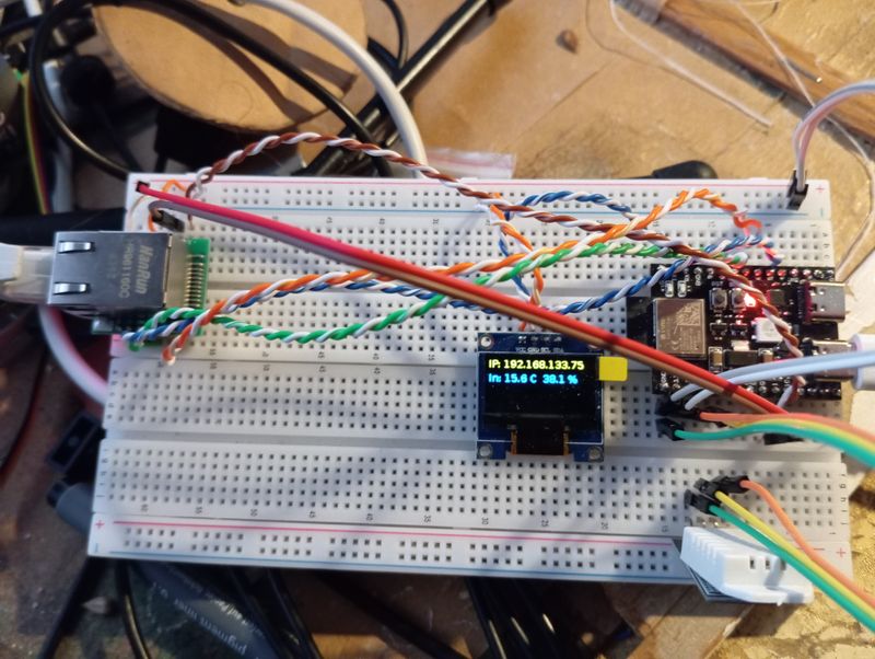
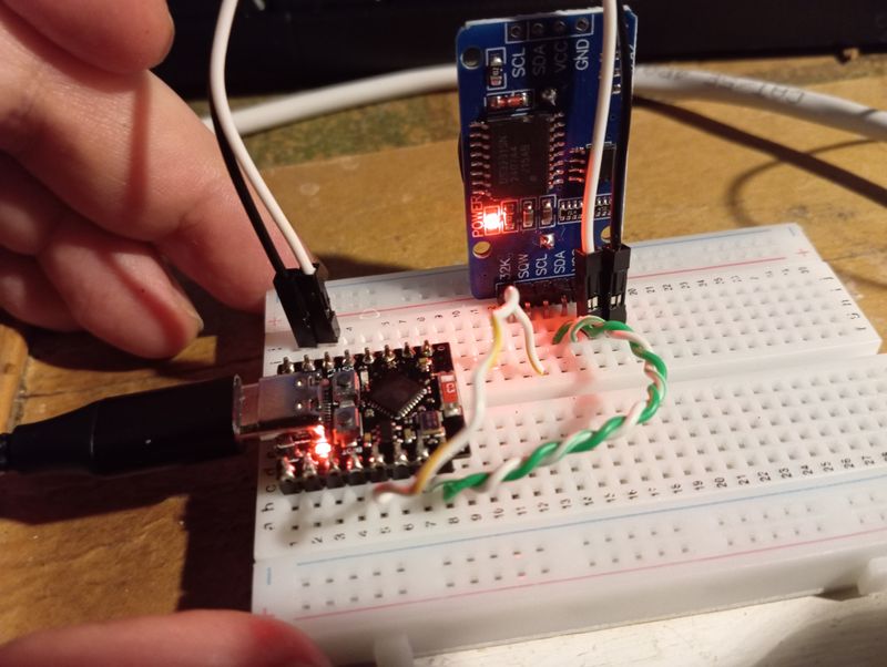
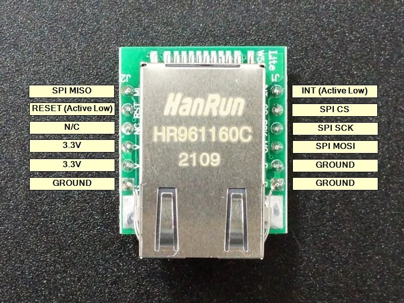
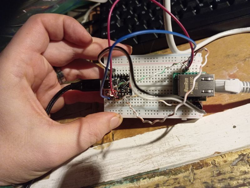
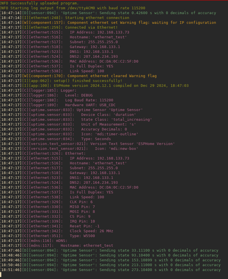
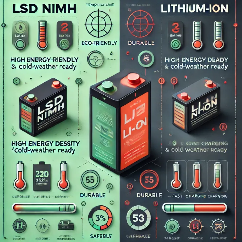

 about capacitors and timing circuits. The tab.webp)