Testing the W5500 Ethernet Controller with ESP32-C3 | LiberIT

Testing the W5500 Ethernet Controller with ESP32-C3
In this post, we document our journey testing the W5500 Ethernet controller with the ESP32-C3 microcontroller. This guide includes detailed wiring instructions, ESPHome configuration, and lessons learned from debugging. If you're exploring Ethernet connectivity for your ESP32-C3 projects, this blog post will save you time and headaches.
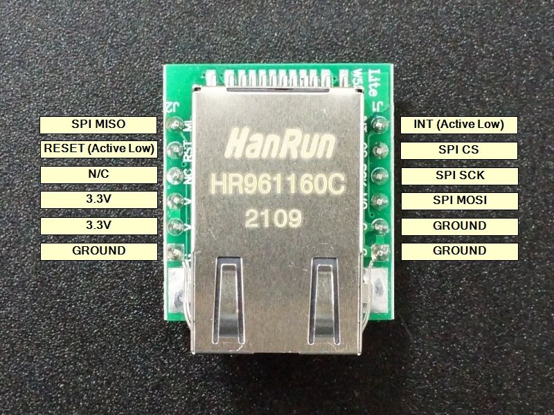
1. Wiring the W5500 Ethernet Controller
The first step was establishing a clear wiring plan. Below is the finalized table of connections, including both DIY/breadboard colors and corresponding RJ45 color mappings:
| Function | DIY/Breadboard Color | Closest RJ45 Color | Recommended Use |
|---|---|---|---|
| Ground (GND) | Black | Green | Common ground for all connections. |
| Power (3.3V) | Orange | Orange | Power supply for microcontroller and peripherals. |
| SPI Clock (SCK) | Blue | Blue | Clock signal for SPI communication. |
| SPI Master Out, Slave In (MOSI) | Green | Green Stripe | Data sent from master to slave in SPI. |
| SPI Master In, Slave Out (MISO) | Yellow | Orange Stripe | Data sent from slave to master in SPI. |
| SPI Chip Select (CS) | Purple | Blue Stripe | Select signal for the SPI slave device. |
| SPI Interrupt (INT) | Brown | Brown Stripe | Interrupt pin for W5500 Ethernet. |
2. ESPHome Configuration
Once the wiring was complete, we moved on to setting up ESPHome for testing. Below is the working ESPHome YAML configuration:
esphome:
  name: w5500_test
  platform: ESP32
  board: esp32-c3-mini

# Enable logging to USB serial
logger:

# Configure Ethernet with W5500 and SPI pins
ethernet:
  type: w5500
  mosi_pin: GPIO8  # Connects to MOSI (Green Stripe)
  miso_pin: GPIO7  # Connects to MISO (Orange Stripe)
  clk_pin: GPIO6   # Connects to SCK (Blue)
  cs_pin: GPIO9    # Connects to CS (Blue Stripe)
  interrupt_pin: GPIO10  # Connects to INT (Brown Stripe)

# Test component (e.g., diagnostics over the serial log)
text_sensor:
  - platform: version
    name: "ESPHome Version"

sensor:
  - platform: uptime
    name: "Uptime Sensor"
3. Lessons Learned
During testing, we encountered several important challenges and insights:
a. Interrupt Pin Requirement
The W5500 requires an interrupt_pin to be defined in the ESPHome configuration. Initially, we missed this detail, which led to errors during the setup process. Once added, the Ethernet controller functioned as expected.
b. Strapping Pin Warnings
GPIO8 and GPIO9 are strapping pins on the ESP32-C3, which can cause unexpected behavior if external pull-ups or pull-downs are attached. These pins should be used with care to avoid stability issues.
c. USB Serial Debugging
ESPHome's logging over USB serial proved invaluable for diagnosing and verifying the Ethernet setup. Always monitor the logs for initialization messages and IP assignment to confirm successful communication.
4. Testing Results
After uploading the ESPHome YAML configuration, we observed the following in the USB serial logs:
- Successful initialization of the W5500 Ethernet controller.
- Assignment of a static IP address (as defined in the ESPHome configuration).
- Real-time uptime sensor values and ESPHome version output.
This confirmed that the W5500 was properly wired and configured for the ESP32-C3.
5. Conclusion
Integrating the W5500 Ethernet controller with the ESP32-C3 is a straightforward process once you’ve defined a clear wiring scheme and configuration. Using ESPHome, you can quickly test and deploy Ethernet connectivity for various IoT applications. Below is a summary of key takeaways:
- Use distinct RJ45 color mappings to avoid confusion.
- Ensure the interrupt pin is properly configured in ESPHome.
- Be cautious with strapping pins (e.g., GPIO8, GPIO9) on the ESP32-C3.
- Monitor USB serial logs for debugging and verification.
By following the steps outlined here, you can confidently set up and test your own Ethernet-enabled projects.
Feel free to share your own findings or improvements in the comments! Happy building!