Let's build a bare-bones amplifier using the absolute | LiberIT

Let's build a bare-bones amplifier using the absolute minimum components so you can hear your electric guitar through your speaker.
Simplest Circuit Design
This circuit will use:
- One transistor as the amplifier.
- A coupling capacitor to pass the guitar's AC signal.
- A resistor for biasing the transistor.
- Your speaker for output.
This is the simplest, working single-transistor amplifier for your guitar.
Components Required
| Component | Quantity | Purpose |
|---|---|---|
| NPN Transistor | 1 | Amplification (e.g., BC337, C1815, 2N2222). |
| Resistor (10 kΩ) | 1 | Biases the transistor's base. |
| Resistor (1 kΩ) | 1 | Acts as the load for the transistor. |
| Capacitor (10 µF) | 1 | Coupling capacitor for the input signal. |
| Speaker (8 Ω) | 1 | Converts amplified signal to sound. |
| Power Supply (9V) | 1 | Provides power to the circuit. |
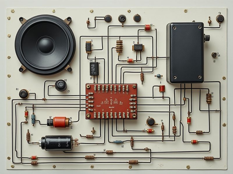
Circuit Diagram
Here’s a simple explanation of the circuit:
    Guitar Signal
        |
       C1 (10 µF)
        |
       R1 (10 kΩ)
        |
       B — Q1 (BC337 or similar)
       E \
        |  \
        |   R2 (1 kΩ)
        |     |
       Speaker
        |
       Ground
- C1: Blocks DC and allows only the AC audio signal from the guitar to reach the transistor's base.
- R1: Biases the base of the transistor so it operates in its active region (amplification mode).
- R2: Acts as a load resistor and limits the current flowing through the transistor to prevent damage.
- Speaker: Connected to the emitter of the transistor to play the amplified signal.
How It Works
- The guitar signal is coupled through C1 to the base of the transistor Q1.
- R1 provides the biasing current to set the transistor into active mode.
- The transistor amplifies the signal at the base and outputs a stronger signal at the emitter.
- The amplified signal drives the speaker, which converts it into sound.
Assembly Instructions
-
Prepare Your Breadboard:
- Connect the positive rail to the +9V supply and the negative rail to ground.
-
Place the Transistor (Q1):
- Insert the NPN transistor (e.g., BC337) into the breadboard.
- Identify the pins: Base (B), Collector (C), Emitter (E).
-
Connect the Resistors:
- R1 (10 kΩ): Connect one end to the base of the transistor and the other end to the positive rail (+9V).
- R2 (1 kΩ): Connect one end to the emitter of the transistor and the other end to ground.
-
Add the Capacitor (C1):
- Connect the positive side of the capacitor to the guitar input (e.g., from the tip of the 1/4-inch jack).
- Connect the negative side of the capacitor to the base of the transistor.
-
Connect the Speaker:
- Connect one terminal of the speaker to the emitter of the transistor (shared with R2).
- Connect the other terminal of the speaker to the ground rail.
-
Connect the Guitar:
- Wire the guitar's output (from the 1/4-inch jack) to the input of the circuit (the side connected to C1).
-
Power the Circuit:
- Connect the 9V battery or power supply to the breadboard’s power rails.
Testing the Amplifier
-
Power On the Circuit:
- Ensure all connections are secure and there are no shorts.
-
Play the Guitar:
- Strum a chord or play a note on your electric guitar.
-
Adjust Connections:
- If you don't hear anything, double-check the polarity of the transistor and the capacitor.
- Make sure the resistors are connected to the correct pins.
What You Should Expect
- The speaker will play the amplified sound of your guitar.
- The volume will be modest since this is a minimal single-transistor amplifier.
- If the sound is faint, try increasing the value of R2 (e.g., to 2.2 kΩ) or using a more sensitive speaker.
Limitations of This Circuit
- This is a basic amplifier for testing and learning. It’s not designed for high-quality sound or loud volumes.
- You may hear some distortion, especially for low frequencies, as it lacks tone control or feedback.
Next Steps
- Improve the Circuit:
- Add a second transistor stage or use your 555 timer to generate tones for testing.
- Build a Tone Control:
- Use a potentiometer and capacitor to create a simple high-pass or low-pass filter.
- Integrate with the Robot:
- Use the amplified signal to trigger actions (e.g., LED indicators, motor movements).
Let me know how it goes or if you’d like to refine this circuit further!